Ok, I always discover my
Silly Mod ( as every is)
I've told you in BAF 2023 video chat that you have wrong ones (majority of projects here calling for SJEP, E as Enhanced ) and it's best to send those nogood ones to OPLDF


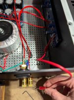
I received my F6 kit today! Unfortunately my fun didnt last long. Im afraid during biasing i dropped one of the multi-meter leads and shorted the left channel resistor to the positive binding post. (like in the picture). I had left one clip on lead on each channel to save time, HA!
Anyone have an idea what i damaged in doing this? It popped a fuse in the process and is now eating through the replacements. I tested the board components, they all seem to be ok. although i have a difficult time getting my multimeter to read the caps.
Anyone have an idea what i damaged in doing this? It popped a fuse in the process and is now eating through the replacements. I tested the board components, they all seem to be ok. although i have a difficult time getting my multimeter to read the caps.
Attachments
it's so easy as checking 2 JFets and 2 mosfets for shorts
if in doubt, then removing pcb from heatsink, then both JFets and both mosfets, checking for shorts outa pcb
if in doubt, then removing pcb from heatsink, then both JFets and both mosfets, checking for shorts outa pcb
Thank you Zen Mod. I found the JFets to be ok, im going to remove them and the mosfets for testing. I discovered my trim pots to be north of 2k. The channel in question does not show 10k when measuring across r9/r10 and p1/p2. Im going to check over the other components more carefully.
Silly Mod ( as every is)
…….it's best to send those nogood ones to OPLDF…
I’m certainly the silliest!
But also suspicious: seems like the people that say “those parts are worthless. Send them to me for proper disposal”
OPLDF = Original Poster Latent Defense Force?
Maybe I’ll just glue them on top of the MOSFETs of the F-6 I’m building for my bro in law so it looks like a “real” First Watt!

Hello all!
I was able to get the parts from last month's release.
My 4U chassis is still from 2021 and I have not opened the box.
I have a few questions:
1) On the bias pot, how do you increase or decrease the value, clockwise or counterclockwise?
2) On the TO-247 insulators, are the ones sold on Amazon good enough? I forgot to buy one when I bought the power supply board.
I already have the power supply parts including the Antek 4218 transformer.
Thank you in advance.
I've built the ACA sometime in 2017.
1) On the bias pot, how do you increase or decrease the value, clockwise or counterclockwise?
The pots can work either way,
It is very important to check (measure) first and to work safely.
Be ready for a rapid increase in bias and be ready to switch off.
A current limiting device like a dim bulb is highly recommended for first power up.
The pots can work either way,
It is very important to check (measure) first and to work safely.
Be ready for a rapid increase in bias and be ready to switch off.
A current limiting device like a dim bulb is highly recommended for first power up.
What Colin wrote. 🙂
Note that if the zeners are relatively low in value (say 6-ish volts), it should be safe to start with the pots at mid point since you're only putting low 3-ish volts Vgs to the mosfets and the IRF mosfets should not draw a lot of current (if at all). You should then be able to adjust the pots slowly to see which direction does what.
Note that if the zeners are relatively low in value (say 6-ish volts), it should be safe to start with the pots at mid point since you're only putting low 3-ish volts Vgs to the mosfets and the IRF mosfets should not draw a lot of current (if at all). You should then be able to adjust the pots slowly to see which direction does what.
Thank you. I saw a YouTube video showing the adjustment. It looks like rotating clockwise decreased the current.1) On the bias pot, how do you increase or decrease the value, clockwise or counterclockwise?
The pots can work either way,
It is very important to check (measure) first and to work safely.
Be ready for a rapid increase in bias and be ready to switch off.
A current limiting device like a dim bulb is highly recommended for first power up.
^^^Dennis Hui has the correct advice. Trimmer pots may vary between models as to whether resistance increases or decreases as the adjustment is rotated clockwise. Test or verify with spec sheet for that model.
^ I agree 100% with the sentiment above, but perhaps for clarity -
With the pots we commonly use and in the applications for which they're used... it varies.
For the pots ... Pin 2 is almost always the wiper pin. I've never found an exception, but I'll still say... almost always. If you measure the resistance between the two outer pins of a pot, you should get the 'stated resistance of the pot'. A 1kOhm pot should measure 1kOhm (or close) between pins 1 and 3.
For a 1k pot, if the pot was perfectly "in the middle", you'd measure 500 Ohms between pin 1 and pin 2 and also between pin 2 and pin 3.
When you adjust CCW for all Bourns pots (of which I'm aware) the resistance between pins 1 and 2 decreases => resistance between 2 and 3 increases.
The big (practical) wiggle is that pots with in-line pins are easy installed "upside down" and many PCB silkscreens don't have the clever icon for the adjustment knob so all users can easily orient them the same way.
So, it is never a good idea (even though I did it in a build guide myself) to use CW or CCW to describe which way to turn the pot. It's always best to note a a preferred resistance measurement between two points on the PCB, IMO.
Again, not disagreeing at all with above, but adding some (hopefully) useful context and clarity.
With the pots we commonly use and in the applications for which they're used... it varies.
For the pots ... Pin 2 is almost always the wiper pin. I've never found an exception, but I'll still say... almost always. If you measure the resistance between the two outer pins of a pot, you should get the 'stated resistance of the pot'. A 1kOhm pot should measure 1kOhm (or close) between pins 1 and 3.
For a 1k pot, if the pot was perfectly "in the middle", you'd measure 500 Ohms between pin 1 and pin 2 and also between pin 2 and pin 3.
When you adjust CCW for all Bourns pots (of which I'm aware) the resistance between pins 1 and 2 decreases => resistance between 2 and 3 increases.
So, for all pots ... the resistance increases, decreases, or stays the same - depending on where you're measuring.Trimmer pots may vary between models as to whether resistance increases or decreases as the adjustment is rotated clockwise. Test or verify with spec sheet for that model.
The big (practical) wiggle is that pots with in-line pins are easy installed "upside down" and many PCB silkscreens don't have the clever icon for the adjustment knob so all users can easily orient them the same way.
So, it is never a good idea (even though I did it in a build guide myself) to use CW or CCW to describe which way to turn the pot. It's always best to note a a preferred resistance measurement between two points on the PCB, IMO.
Again, not disagreeing at all with above, but adding some (hopefully) useful context and clarity.
This also veers into an area where people have strong opinions, but...2) On the TO-247 insulators, are the ones sold on Amazon good enough? I forgot to buy one when I bought the power supply board
I've used these on all most of my projects and am running on 4 years without a hitch.
https://www.amazon.com/gp/product/B09FY1FR15/ref=ppx_yo_dt_b_search_asin_title?ie=UTF8&psc=1
With this heat sink compound.
https://www.amazon.com/gp/product/B0044NI2M2/ref=ppx_yo_dt_b_search_asin_title?ie=UTF8&th=1
Why not just buy Keratherm from DIY Store? It is equivalent in performance to alumina ceramic oxide and thermal compound, but it is less hassle to use inasmuch as thermal compound requires more work to properly measure out and spread. In addition of removal of the transistor is necessary, removal/cleanup of the thermal compound can be a messy and frustrating task.
At the time, every penny counted. Having bought the large box of Chiclets, I continue to use the supply. Both options work just fine.
Yes, the goop is goopy, but it's also kinda fun to smear around.
Yes, the goop is goopy, but it's also kinda fun to smear around.
Thank you all for the replies.
I checked the parts earlier that came with the kit. I noticed that the zener diode included is the 9.1 volts. Is it okay to use this? Can you explain the purpose of the zener diode?
I checked the parts earlier that came with the kit. I noticed that the zener diode included is the 9.1 volts. Is it okay to use this? Can you explain the purpose of the zener diode?
The zenner mod that many people have used is detailed on post 27, page 2 of this guide by mighty Zen Mod.
This is the modified schematic.
Another well regarded modification which is much simpler to do on first build is to replace the Zenners with three green LEDs in series. with something like 3k3 resistors. This is also documented. in this thread.
"post-6849120"]https://www.diyaudio.com/community/...y-dumbest-idea-yet.348969/page-5#post-6849120[
- Home
- Amplifiers
- Pass Labs
- F6 Illustrated Build Guide