@pestoman
Take your multimeter in continuity mode and touch one probe to the back of an output transistor while touching the other probe to the three pins (one at a time). It will become apparent why we use an insulator between the back of the transistor and the sink.
Edit for clarification: this test would be done with the transistor out of circuit.
Yes, a faulty insulator would cause issues and ruin your day.
Edit:
Mighty One beat me to the punch. My typing is pretty slow on this phone.
Last edited:

OR you’re using a transistor with a non-conductive back, which would be the case if you built the ACA mini.only if you see big IXYS pucks in amp construction, there is no need for isolator, it's already done in part body itself
Pestoman, you can do it! I can only offer moral support, sending good vibes your way.
Hi All,
Building a F6 for the first time, maybe someone can help me troubleshoot. The bias at one board cannot be increased higher the then 0.180 v and the otherone stays on zero. What is the best way to check what component is giving the troubles?
Done so far:

Needs to trim of the power cables.

Building a F6 for the first time, maybe someone can help me troubleshoot. The bias at one board cannot be increased higher the then 0.180 v and the otherone stays on zero. What is the best way to check what component is giving the troubles?
Done so far:
- PSU is giving 26 volts
- Tried to increase or decrease the offset
- The temp of the heatsinks are increasing till from 19 to 21 degrees.
Needs to trim of the power cables.
We can start with some standard stuff:
Assuming you are using this schematics from page 1: https://www.diyaudio.com/forums/gallery/data/500/F6_DIY_SCH.gif
1) Please specify R7, R8 resistor and Z1, Z2 zener values you used.
2) Please measure the voltage drops across Z1 and Z2.
3) Please measure voltage drops across R1 and R2 and the DC offset
Can you please confirm that on the PCBs, you get the expected voltages at V+ and V- (referencing ground).
Also, how much had you turned P1 and P2 when you wrote that you couldn't set the bias level. Did you hit the end of the trimmer's adjustment range?
Another helpful measurement is the Vgs of both output mosfets. The G and S are the two outer pins of the mosfets.
Both good points.
I would second Ben's suggestion to measure the Vgs voltages of the IRFP240. (Be careful with the probes / clips though!)
The mosfets don't really turn on until you see 3-ish volts between the two outer pins. And these voltages are
controlled by turning P1 for Q1 and P2 for Q2.
I would second Ben's suggestion to measure the Vgs voltages of the IRFP240. (Be careful with the probes / clips though!)
The mosfets don't really turn on until you see 3-ish volts between the two outer pins. And these voltages are
controlled by turning P1 for Q1 and P2 for Q2.
Thank you for the quick responses!
Board 1: with the low bias
1) Please specify R7, R8 resistor and Z1, Z2 zener values you used.
R7: 10k
R8: 10k
Z1: 5.1v
Z2: 5.1v
2) Please measure the voltage drops across Z1 and Z2.
Z1: 4.55
Z2: 4.47
3) Please measure voltage drops across R1 and R2 and the DC offset
R1 0.17
R2 0.22
DC Offset: 2.10
Can you please confirm that on the PCBs, you get the expected voltages at V+ and V- (referencing ground).
How to measure this on the PCB?
Also, how much had you turned P1 and P2 when you wrote that you couldn't set the bias level. Did you hit the end of the trimmer's adjustment range?
Yes i turned the trimmers will the end (it gives some ticks it seems) after that i tried 10 turns extra, when i do the pots clockwise the bias will lower anti clockwise will increase the bias till the max of 0.200.
@Dennis, @Ben Mah
Q1: 4.21v
Q2: 4.22v
Temp of the heatsink is 26c.
Board 2 with no bias:
1) Please specify R7, R8 resistor and Z1, Z2 zener values you used.
R7: 10k
R8: 10k
Z1: 5.1v
Z2: 5.1v
2) Please measure the voltage drops across Z1 and Z2.
Z1: 4.53
Z2: 4.7
3) Please measure voltage drops across R1 and R2 and the DC offset
R1: 0
R2: 0
DC Offset: 0.04
@Dennis, @Ben Mah
Q1: 3.03
Q2: 0.16
For board 2 it is maybe the pot on the bias what not making contact or not working at all?
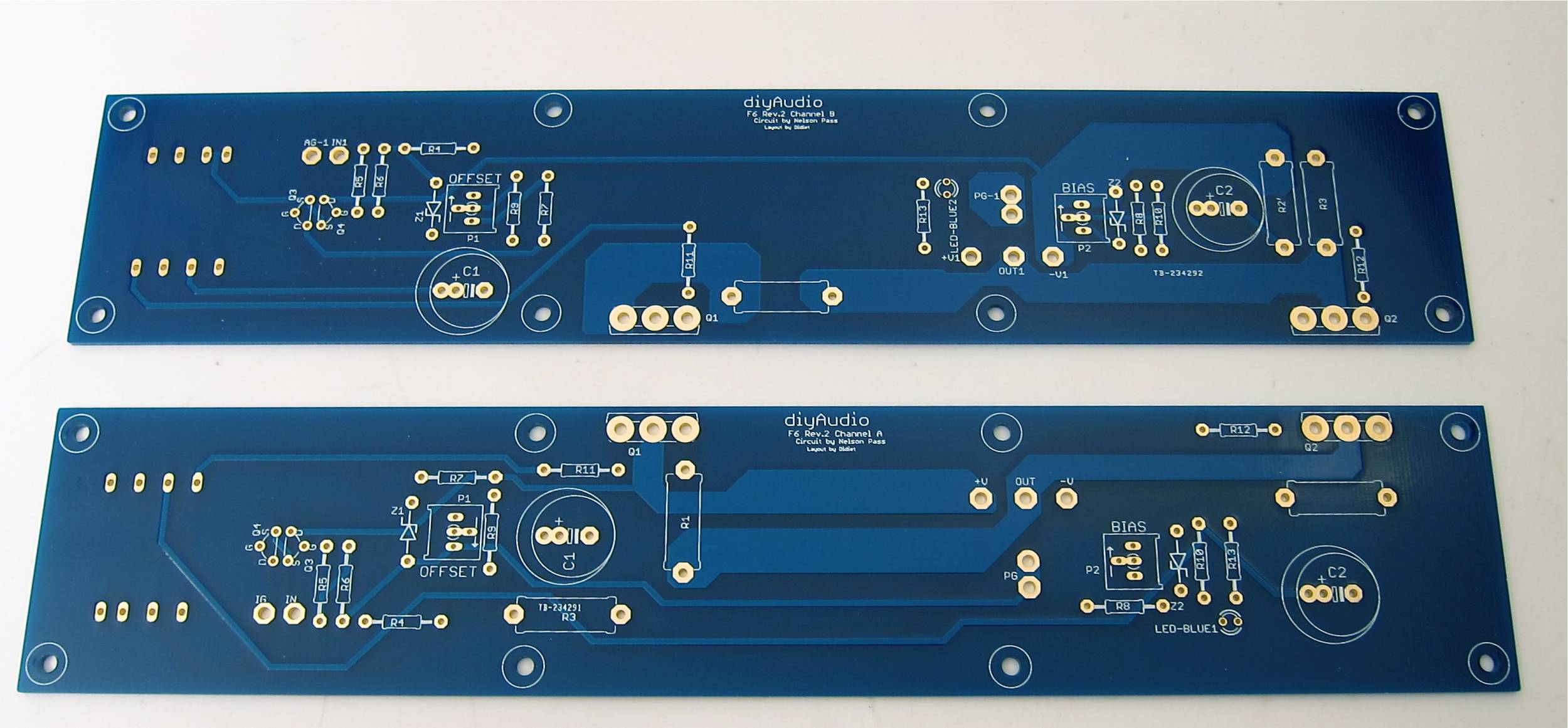
For the power supply voltage on the PCB, please refer to this photo: https://www.diyaudio.com/archive/gallery/data/500/F6PCB.jpg
Have you ground (black) meter probe on PG (resp. PG-1) and measure with your positive (red) probe at +V (resp +V1) and -V (resp -V1)
You should see, say +24 for +V and -24 for -V.
On board #2, does the Q2 Vgs voltage change when you adjust P2? Turn it in both directions at least a few turns to see. If you can get this to change then you might have just turned the pot in one particular direction which turned the bias down. (You can't always count on direction). If you can't get that voltage to change with P2 adjustment then soldering or a bad P2 might be in play.
On board #1, can you adjust P1 to get the DC offset close to zero?
I think your Z1 and Z2 voltages are kind of low. You may need to increase them and decrease R7 and R8.
On board 1 I checked the volts and they are +24 and - 24, I managed to increase the offset from -2.10 till zero and it stays stable.
I have also the 33b marked zeners is that helping for increase the z1 and z2 or need i decrease the R7 and R8 for that?
On board 2 i tried to adjust the P2 but no differents in the voltage, maybe i did a wrong measure the first time i get now 1.93v
I have also the 33b marked zeners is that helping for increase the z1 and z2 or need i decrease the R7 and R8 for that?
On board 2 i tried to adjust the P2 but no differents in the voltage, maybe i did a wrong measure the first time i get now 1.93v
Board 1: As Dennis said, the zeners may need to be increased in voltage. If 33b zeners are 33V, that is too high. Look for zeners in the neighbourhood of 6V or so. You may be able to get by without reducing R7 and R8 if the zeners are around 6V.
Board 2: The voltage at the zeners is not getting to the mosfet gates. Check the soldering of the pots, R9, R10, R11, R12, mosfets and transformer.
Board 2: The voltage at the zeners is not getting to the mosfet gates. Check the soldering of the pots, R9, R10, R11, R12, mosfets and transformer.
One thing that I neglected to mention is that the Vgs voltage you measure will respond slowly to adjustments of the pots.
It's good that you are seeing some voltage (1.93V) for Q2. Try turning P2 a few times and wait a bit and see if the measured voltage changes.
Did you get the f6 kit from the store? https://diyaudiostore.com/collections/kits/products/f6-board-transformer-kit
If so, the 33B zeners are apparently 6.0V ones which should do the trick.
Thanks for your help so far, I bought the f6 kit at the store, so i have the set 33B zeners.
I will going to try that to swap them. Will report the results back hope next week.
I will going to try that to swap them. Will report the results back hope next week.
A quick warning: Please make sure you dial back down the trimmers before powering up with the new zeners. Otherwise you risk starting up at very high current levels.
Changing the zeners was doing the trick. Thanks so far!! Board 1 is stable with a 500mv and 0 offset.
Board 2: replaced also the zeners and the bias is at 500, only the offset is -24v and not getting it higher. Any ideas?
Board 2: replaced also the zeners and the bias is at 500, only the offset is -24v and not getting it higher. Any ideas?
- Home
- Amplifiers
- Pass Labs
- F6 Illustrated Build Guide