Pretty nice. They kick my box around the warehouse floor for two days before sending it out... God forbid it comes UPS...
^ HA! Same here. I'm glad they package things pretty well.
I'm fortunate that DigiKey and Arrow have warehouses in my neck of the woods....
With that said, Mouser has been very good to me. Just joshing that yep... between them and the delivery service, most of my packages find the doorstep looking like they were drug behind the truck.
I'm fortunate that DigiKey and Arrow have warehouses in my neck of the woods....
With that said, Mouser has been very good to me. Just joshing that yep... between them and the delivery service, most of my packages find the doorstep looking like they were drug behind the truck.
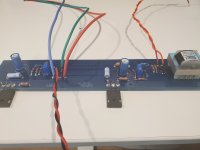
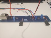
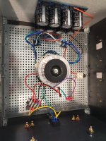
Man, I am bummed. This is my 2nd from the ground-up attempt at an F6 Build (at least the boards), and for the life of me I cannot figure out what is going wrong. For the power supply, it's the same one I've been using for months. With nothing hooked up to it, I'm getting 25V plus and minus, no issues at all. I quadruple (literally 4 times) tested and checked every single component on the F6 boards, was scrupulous on the soldering, and hooking everything up. When I hook up one channel to power, I get nothing, no light no signal, when I tested the other channel, I got the led to light up (after switching it around), then as I was figuring out which resistor to start measuring bias, I got smoke from that board, and immediately blew a fuse. I built an Aleph J, 2 ACA's, and a B1 Nutube preamp, all with really no issues, something about this board is messing with me. The only thing I can possibly think is that even though I shut off the mains power, while I was switching the LED around, the board was still attached to the PSU, so there may have been some very quick connections and shorts to the circuit. When I realized this, I immediately disconnected the 3 wires to the PSU, but maybe I damaged something in the process? I'd appreciate any help here, I am so beyond frustrated with this amp, maybe I just need an early beer. I can send pics. Thank you in advance.
Yep, always use DBT or variac on first power up. Also figure out what voltages to monitor, what to adjust, and hook up the meters and have them turned on before power up.
What value zeners Z1 and Z2 were used? Also how had you set the pots P1 and P2 prior to power up?
Zeners were straight from the diyaudio store 9.1V, along with the mosfets from them as well. I had not touched P1 and P2 prior to power up.
okay actually even the power supply doesn't work now after replacing fuses. I am back to the drawing board.
The PSU is dead? Doubtful. Did you forget to plug the AC cord back in after swapping the fuse? It’s easy to overlook the big picture when focused on the small stuff and flustered.

I hate to ask the simple questions like is it plugged in, but… I know on one of my chassis the fuse holder was a little trickier to get seated than the other.
No it's a legit question for me in this state, for sure. Thanks everyone. But yeah, it's plugged in. One question. (When it's not plugged in) should I have connectivity between the IEC mains input, like the 3 prong AC inputs and the Euroblock connectors at the top of the power supply board, after the transformer, rectification and capacitors? I don't, but checking. I am seeing connectivity between my +, -, and ground AC mains in through to the terminal block, and on the ground to the thermistor when the power switch is on (trying to see if something is funky with my fuses). Don't know if I'm supposed to see connectivity beyond that. When I plug in and turn on, I get nothing.
No direct connection between PS board and IEC because of the power transformer. You should get direct connection from power cord connected to IEC and the terminal block in the chassis that is connected to the IEC. So check that both prongs of the power cord has direct connection to the terminal block. That will let you know that the fuse is installed correctly and is not blown.
You can also check for AC voltage at the AC side of the rectifier blocks and check for DC voltage on the DC side of the rectifier blocks.
You can also check for AC voltage at the AC side of the rectifier blocks and check for DC voltage on the DC side of the rectifier blocks.
when everything is OK on primary side, with fuse intact and power switch ON, you can measure Rdc directly on mains cable, between L and N, and see few ohms of primary Rdc, plus 10 or so ohms of NTC in series
so, all most probably good if you can read 12-20 Ohms there
so, all most probably good if you can read 12-20 Ohms there
Good grief, a wire had popped out of a crimped Panduit connector when I was pulling everything out to test. I'm so sorry everyone. I may just go back to my beautiful Aleph J and chill with that for now 🙂


Zeners were straight from the diyaudio store 9.1V, along with the mosfets from them as well. I had not touched P1 and P2 prior to power up.
9.1V zeners can be bad news if the trimmers were set for maximum gate voltage. 9.1V at the mosfet gate is essentially a short from drain to source. If the trimmers were left in the midway position from the factory, then probably no issues. But this is diy and trimmers may be set haphazardly, and when combined with other possible issues, it can cause a lot of grief.
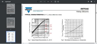
If more gate voltage is desired, I would think a small boost in the zener voltage is safer. Looking at the IRFP240 specification sheet, even 6V at the gate of a cold IRFP240 will get 10A of current.
Attachments
- Home
- Amplifiers
- Pass Labs
- F6 Illustrated Build Guide