
Board makring
I've completed the board (Rev 2) and have noticed some imperfections with elements markups.
1. There are 2 resistors not marked at all, R1 on one board and R2 on another one.
2. Elements marks are placed under elements themseves, so once element is placed, you can not see and verify correctness visually.
3. LED do not have polarity marks at all. You have to trace the board and schema.
I'm a newby just starting on my F6 - I comparing my layout with the phtos in the build guide it looks like I have R1 and R3 reversed - The Board is missing some labels but I think I am right based on the Schematic (But I'm no expert) -
I am thinking it is just his resistors look different - R1 = .56 3W R3 = 100 3W I have attached pictures of my boards
Looks good to me. 🙂 If you stuff the Dale resistors with the value facing up - it will save you a ton of time if you're ever worried that you may have mis-stuffed a board. Yes, both the R1 (Black in the build guide) and R3 (Blue in the build guide) look different than the ones provided in the kit.
Congrats on getting started, using the schematic, and tracing the boards. 😀
Have fun!
Hello KampfKeks3000,
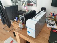
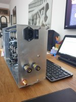
Love those chassis!
It is your design and did you build them yourself?
Hello @ mqb1965,
@ quafro
yes it's my design 🙂
I made them by my self in my tiny basement. (With a hand saw and hand drill)
Bending the aluminium sheets was pretty tricky... I had a few tries.
First I wanted to lay them flat on the table, but the produced heat was more than expected so I had to put them vertically.
Attachments
Last edited:

@ sov
Thank you very much 🙂
When I'm finished with the chassis, I will anodize some of the parts in silver.
Thank you very much 🙂
When I'm finished with the chassis, I will anodize some of the parts in silver.
When I'm finished with the chassis, I will anodize some of the parts in silver.
Gorgeous work! Can't wait to see the finished product.
Hey guys,
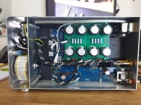
I finally finished my F6 mono amps.
Unfortunately I had a bit of an accident while switching from my first chassis version to the second one....
I mixed up + and - going to the board...
That cooked one of the 1000uF capacitors.
I replaced both capacitors to be safe, but now I have a harsh sound when turning the amp off and a silent hum when turned on.
Could someone help me sorting out, which part could be damaged, too.... apart from the capacitors? 🙁🙁🙁
Thank you very much.
Has anyone a clue, what part could be damaged after my stupid accident?
I hope the jfets are okay....
They are original Toshiba 🙁
Have you checked the DC conditions, that is the first starting point? If the DC offset and bias set correctly then the input FET's are likely damaged.
If the offset/bias is incorrect then the output stage has suffered. Check that R1 and R2, R3 and R4 are intact.
If the offset/bias is incorrect then the output stage has suffered. Check that R1 and R2, R3 and R4 are intact.
Hi Mooly,
Than you for your reply.
I can set bias and Offset properly and it remains stable.
I have another matched quad jfets.... seems that i have to replace them 🙁
Than you for your reply.
I can set bias and Offset properly and it remains stable.
I have another matched quad jfets.... seems that i have to replace them 🙁
I think you have to try. All the other component values are to high to pass significant current under reverse polarity conditions.
Has anyone a clue, what part could be damaged after my stupid accident?
I hope the jfets are okay....
They are original Toshiba 🙁
Well , i did the same stupid mistake time ago , the 0.47 and 0.56 ohm resistors got cooked , all the other components were ok , including jfets
even if the resistors measure ok , you should better change them 😉
.
Last edited:
@ fabrice63
Wow...You mean, maybe the 3W Resistors got cooked?
I will check that.... unfortunately I don't have spare parts of them left...
@Mooly
I will check the resistors first, they are way cheaper 😉
Otherwise i will replace the jfets as recommended.
Many thanks
Wow...You mean, maybe the 3W Resistors got cooked?
I will check that.... unfortunately I don't have spare parts of them left...
@Mooly
I will check the resistors first, they are way cheaper 😉
Otherwise i will replace the jfets as recommended.
Many thanks
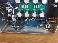
Small update...
I replaced the 0.47 and the 0.56 Ohm resistors with some of the 0.47 Ohm Panasonic's from my PSU...
Hum and turn off noise are still present, but it was worth a try.
Seems Mooly was right about the jfets.
I replaced the 0.47 and the 0.56 Ohm resistors with some of the 0.47 Ohm Panasonic's from my PSU...
Hum and turn off noise are still present, but it was worth a try.
Seems Mooly was right about the jfets.
One thing that might be worth mentioning is that the two output FET's (IRF240's?) have parasitic diodes across drain and source and that means they should have conducted heavily effectively shorting out the power supply if the polarity was incorrect.
It might be worth you making sure the power supply is still all good and that the rails are clean.
Scope?
It might be worth you making sure the power supply is still all good and that the rails are clean.
Scope?
So the heavy current peak could have killed the psu Filter caps?
That would explain the hum.
I dont have a scope... but maybe i can get one for testing.
That would explain the hum.
I dont have a scope... but maybe i can get one for testing.
As Mooly said , when we invert the polarity , both the + and - goes to the 0 through the Mosfet diode , the current is 20 Amps or so , if the inverting process is short ( less than 10 sec ) , the output resistors burn quickly , if it last longer , you could have more issues in the PSU
in case of short duration inversion the CL 60 should damped the current
.
in case of short duration inversion the CL 60 should damped the current
.
Yes, I was on a budget. After reading from a post, I told my wife that the whole project was going to cost about $250. I misread it. Further, I was so saturated with so much information I was getting confused. So I had to walk away from it for a while and came back with a sense of clarity. In summary, I just ordered 4U Deluxe. And I am a novice builder and this chassis will be great for me. And my wife is on board!You specifically mentioned you're on a budget, but the back panel / mounting kit made my life soooooo much easier as a novice builder.
I am now building my BOM at the "M" electronics. I've gathered parts by looking at Jim's pictures. Please share your experience of what parts worked the best and etc. I am thinking of buying 20000uf or bigger caps instead of 15000uf since I am going to work with bridge rectifiers. I found a few mil spec rects on line. This is my first solid state amp build ever. And I am very excited. Any insights and suggestions will be welcomed. Thank you!
Congratulations! Even better that your wife is on board. 😀
I totally understand being saturated with information.
I can't offer what parts are best or work better than others. Others are far more qualified.
I copied the BoM from the store kit. It increases my likelihood of a successful build, and I know they use excellent parts. I can tweak any time as I learn more. I will be trying 2Picodumbs's LED modification at some point. Even if you install the Zeners initially, they are easily swapped out.
Enjoy the build!!!
- Home
- Amplifiers
- Pass Labs
- F6 Illustrated Build Guide