I don't think cl60 is necessary there, I use to connect transformer ground, not CET, direct to ground star. From PSU ground through cl60 to ground star.
I see. Thank youI don't think cl60 is necessary there, I use to connect transformer ground, not CET, direct to ground star. From PSU ground through cl60 to ground star.
I don't think cl60 is necessary there, I use to connect transformer ground, not CET, direct to ground star. From PSU ground through cl60 to ground star.
Yup!
Hi @ Mooly,
hi @ Spe@kerBox,
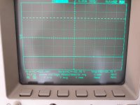
finally.... I have some Scope Pictures.😀
The PSU seems to be okay.
But, have a look by yourself.
What do you think?
Thank you very much for your help 🙂
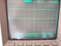
PS: The 300-600mV peak peak seem to be permanent noise.
hi @ Spe@kerBox,
finally.... I have some Scope Pictures.😀
The PSU seems to be okay.
But, have a look by yourself.
What do you think?
Thank you very much for your help 🙂
PS: The 300-600mV peak peak seem to be permanent noise.
Attachments
-
 Negative Rail With Load.JPG161.6 KB · Views: 233
 -
 Speaker Terminals With Bridged JFET.JPG180.1 KB · Views: 133
 -
 Speaker Output Without JFET.JPG183.6 KB · Views: 234
 -
 Positive Rail Without Load.JPG176.6 KB · Views: 224
 -
 Positive Rail With Load.JPG164 KB · Views: 227
 -
 Negative Rail Without Load.JPG181.1 KB · Views: 229
Last edited:
Hi @ Mooly,
hi @ Spe@kerBox,
finally.... I have some Scope Pictures.😀
The PSU seems to be okay.
But, have a look by yourself.
What do you think?
Thank you very much for your help 🙂
PS: The 300-600mV peak peak seem to be permanent noise.
Not sure that's right. My F6 all buttoned up but I don't recall seeing that kind of noise on the rails. Wondering if something is not right.
Not sure that's right. My F6 all buttoned up but I don't recall seeing that kind of noise on the rails. Wondering if something is not right.
No no...
I meant, the 300-600mV are present on the Oscilloscope even when no Kabel is connected.
No no...
I meant, the 300-600mV are present on the Oscilloscope even when no Kabel is connected.
Oh, sure your probes are OK?
It's the same with both probes...
They are 10:1 Probes.. If I disconnect the probe i get only 31-62mV.
I'm not that familiar with this device :/
They are 10:1 Probes.. If I disconnect the probe i get only 31-62mV.
I'm not that familiar with this device :/
Hi @ Mooly,
hi @ Spe@kerBox,
finally.... I have some Scope Pictures.😀
The PSU seems to be okay.
But, have a look by yourself.
What do you think?
Thank you very much for your help 🙂
PS: The 300-600mV peak peak seem to be permanent noise.
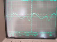
With scope probe ground lead and tip shorted the trace should be flat, no noise at all.
Now check the calibration on the scope using the 'CAL' output on the front.
Check whether you are using a 1:1 probe or a 10:1 divider type... which I see you mentioned.
Now connect the scope probe ground lead to the ground terminal of the amplifier board. Be careful the clip doesn't twang off and short anything.
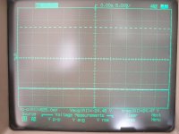
Use AC coupling on the scope input and see what you have when looking at the positive and then negative rail. Remember to mentally account for the probe being a X1 or X10 when looking at the peak/peak voltage.
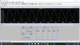
This is the kind of thing you should see for a current draw of 1.3 amps on the rail. The ripple is around 100mv peak to peak and the frequency is twice your mains frequency. I've given each cap an ESR of 0.03 ohms which is perhaps a bit high but that only makes the ripple worse... and its still low with all that capacitance.
Attachments

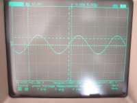
Yes, that looks reasonable as long as the peak to peak value is low.
You have a X10 probe in place? so I would expect the scope to be on say 2mv/Div to display 'five squares worth' of amplitude... so 100mv peak to peak.
Is that what you have ?
If so then the PSU looks fine 🙂
You have a X10 probe in place? so I would expect the scope to be on say 2mv/Div to display 'five squares worth' of amplitude... so 100mv peak to peak.
Is that what you have ?
If so then the PSU looks fine 🙂
Yes, the peak to peak is around 100mV.
Its a 20mV scale.
The10x Probe is automatically recognised.
Its a 20mV scale.
The10x Probe is automatically recognised.
Hi Mooly,
Would you replace the resistors on the PSU board, just to be sure?
Or does it measure well enough?
My next step would be replacing the MOSFETS.
I orderd a new matched set irfp240.
Thank you very much
Would you replace the resistors on the PSU board, just to be sure?
Or does it measure well enough?
My next step would be replacing the MOSFETS.
I orderd a new matched set irfp240.
Thank you very much
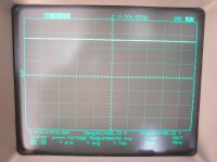
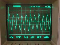
OK 🙂 And the second picture is the negative rail ? So both are similar ?
If so then its looking like we are back to the main amp board for the fault and so I think a process of elimination now.
I'll have another think and look in again tomorrow 🙂 but it's good to prove the PSU OK with the scope. It has removed any doubt over that.
If the power FET's were damaged you would think they would show other issues and not bias up correctly and maintain the correct DC conditions... and yet they do.
And yet there is not much left. I think you are just going to have to replace all these parts to eliminate doubt, and yet that is just so unscientific it goes against the grain 🙂
Hi Mooly,
Would you replace the resistors on the PSU board, just to be sure?
Or does it measure well enough?
My next step would be replacing the MOSFETS.
I orderd a new matched set irfp240.
Thank you very much
The 0.47 ohms will be fine if they measure OK. They could only go high in value and that would actually decrease the ripple as the resistors and the following caps form a simple filter. The higher the R the lower ripple.
In any case your measured ripple agrees with the simulation. I don't see any problem there.
The FET's are cheap enough to try and I think we also have to try the JFET's
When you shorted the transformer out did you try linking out pins 7 and 5 and pins 6 and 8 to remove the secondaries from the circuit?
Tomorrow 🙂
Attachments
Yes, the pictures are from Pos and Neg rails.
Values are similar.
I Think i have to replace Part After Part to sort it out, too.
But i know what you mean by "unscientific" 😉
Now I have to wait for my new parts....
I will keep you up to date 🙂
Values are similar.
I Think i have to replace Part After Part to sort it out, too.
But i know what you mean by "unscientific" 😉
Now I have to wait for my new parts....
I will keep you up to date 🙂
No, i bridged between source and Gate of the jfet to pull the input windings Down.
Hmmm....I could try that, too. 🙂
Maybe tomorrow or the day After.
Hmmm....I could try that, too. 🙂
Maybe tomorrow or the day After.
your speakers matching
I am still waiting for my parts to arrive. My goal it to put it all together by this weekend. BUT, my pre is out of commission. Thus, I need to patiently wait for my Nutube board to arrive. In the mean time I wanted to ask questions to those who hacve finished the project ahead of me. Questions are: What speakers are being driven by the F6, efficiency, impedance, etc? Did you have to adjust anything to accommodate the F6? My woofers are 16ohm and it's highly efficient and with a 8 ohm compression drivers. I wander how the F6 would tame my wild speakers, especially the compression drivers.
thanks
Last edited:
- Home
- Amplifiers
- Pass Labs
- F6 Illustrated Build Guide