. That is a monster set up! 😀 I hear that early models need some clean power to drive them.I'm currently driving my Cornwalls,105db speakers
I am assembling my F6 kit and the DIYaudio kit has 5.1v diodes and 6v diodes. I saw something about the numbers but they are too small for me to see any numbers. I also read about building a test rig
When I measure them with my mutimeter some of them have a reading of .70 something and other are .72 something I am thinking the lower ones might be the 5.1 volt ones. Would this be a proper assumption?
Plus I read someplace I probably want to use the 5.1s
When I measure them with my mutimeter some of them have a reading of .70 something and other are .72 something I am thinking the lower ones might be the 5.1 volt ones. Would this be a proper assumption?
Plus I read someplace I probably want to use the 5.1s
Unfortunately the meter is only telling you the forward voltage of the diode (~0.7V).
You need something to give the zener some current and measure the voltage
drop across it. You can find a setup here (Scroll down to "How to Test a Zener Diode with a Voltmeter of a Multimeter"):
How to Test a Zener Diode
Post #1900 may have the info about the labeling of the parts with the kit:
https://www.diyaudio.com/forums/pass-labs/277850-f6-illustrated-build-guide-190.html#post6207515
You may want to use the 6V ones since some members found 5.1V a bit low for
biasing.
The measurements you took may not indicate properly.
You can measure them, but try this first... I do it all the time... in restaurants... for parts... you name it.
If you got the kit, it may be written on the tape. If not, take a pic of the part with your phone... or just use your phone's zoom...
Z1/2 5.1v Zener (4) (Marked "31B")
Z1a/2a 6.0V Zener (4) (Marked "33B")
Edited to add... LOL! Or you can forego my "old guy" phone method and measure per Dennis' suggestion. 😀 He's FAST!
HTML:
If not, take a pic of the part with your phone... or just use your phone's zoom😀
The phone thing is brilliant - I never thought of it - it didn't work I couldn't read anything but I'll definitely use it in the future -- guess I'll track down a battery and resistor
I had problems with the 5.1V Zeners, too.
6.2V Zeners and 3.3k resistors worked for me perfectly 🙂
6.2V Zeners and 3.3k resistors worked for me perfectly 🙂
Good folks, here is another option to check out:
Dumb Biasing Mod, applicable to F6 and other Papa Amps. Possibly My Dumbest Idea Yet
The idea is to use a voltage reference with a negative tempco, in order to offset the positive tempco of the output Mosfets.
Dumb Biasing Mod, applicable to F6 and other Papa Amps. Possibly My Dumbest Idea Yet
The idea is to use a voltage reference with a negative tempco, in order to offset the positive tempco of the output Mosfets.
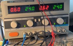
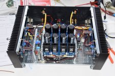
Just another F6 that came to life a month ago...biasing worked like charm - using a 6.1V zener and, can't stress this more, the support of a 2-channel lab power supply. Biasing with a current limiter is really a nice helpful thing 😀
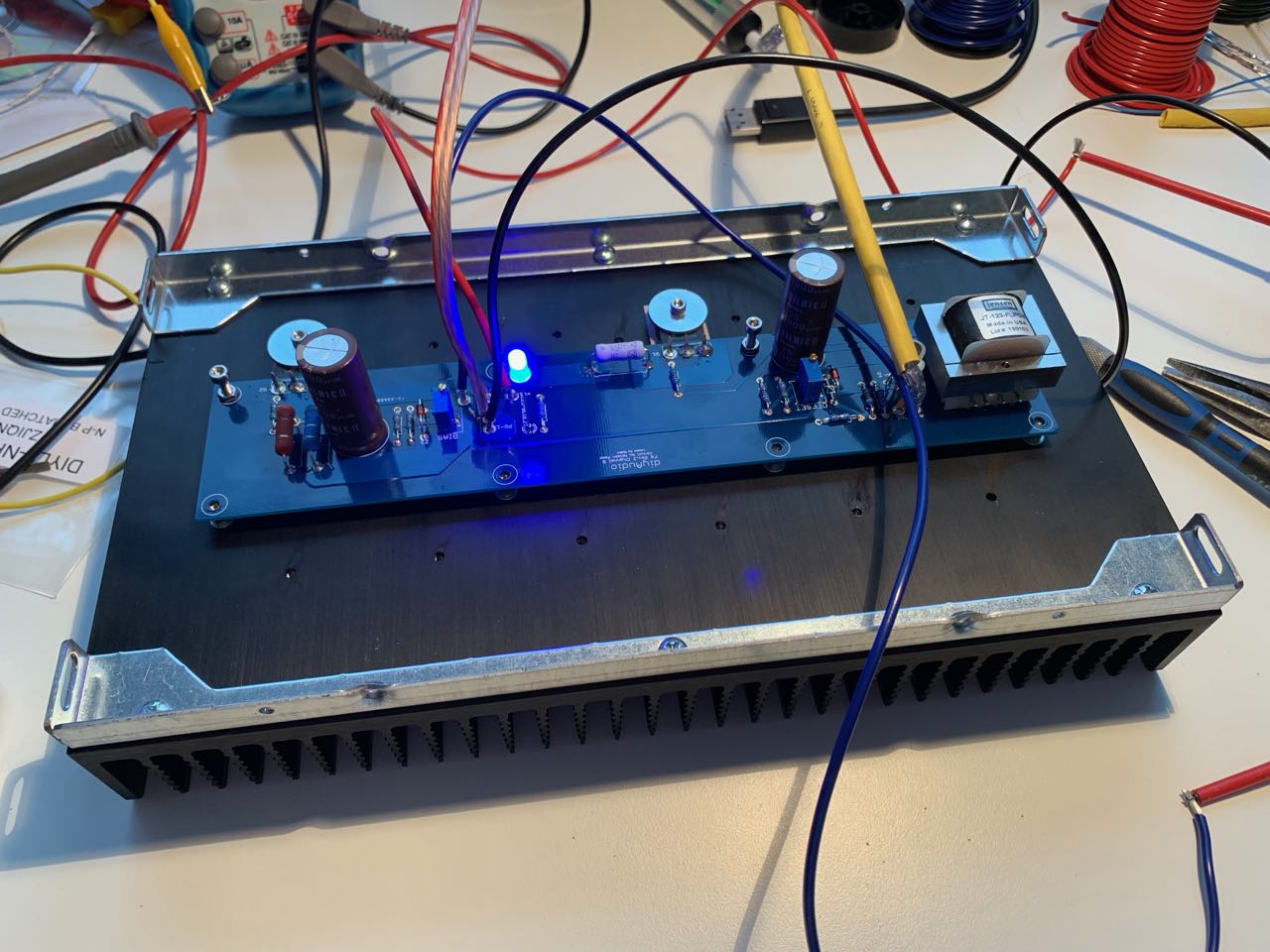

Above being at 0.6 A of bias on one of the channels - I got both up to 0.95A and left it there - after a few hours of idling with the cover plate on I ended at 50 degrees heat sink temp behind the output mosfets, while the drain pins were around 70 degrees - I guess that's good enough...
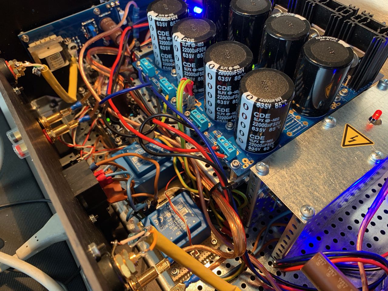
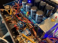
A little bit cramped interior, with the speaker protection board on the right hand side of the PSU, and the soft start on the left hand side - put a divider and later on a cover around the soft start in order to avoid accidental touching of high voltage parts.

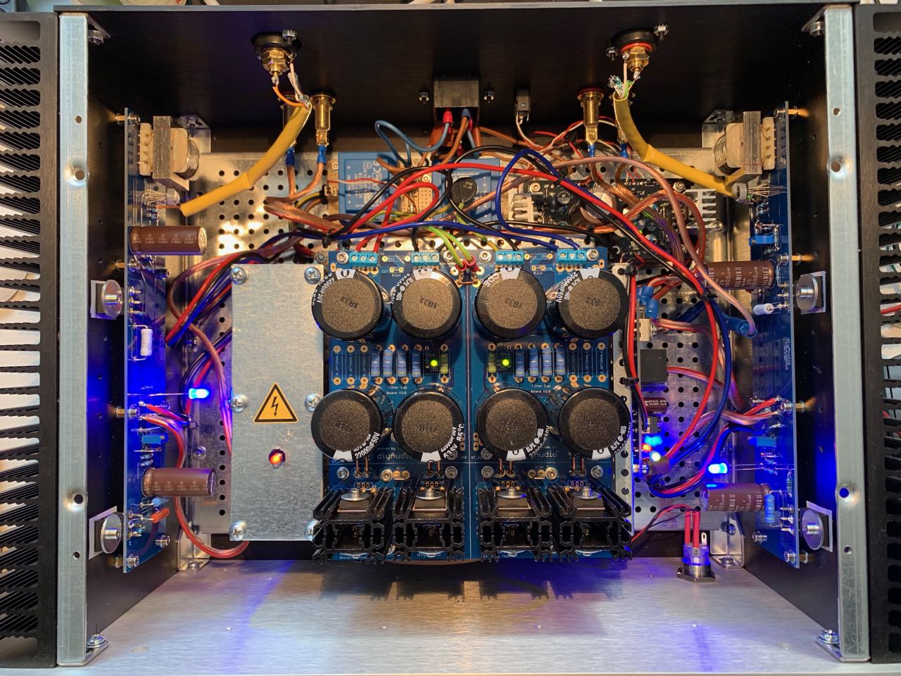
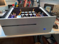
Finally, the face plate and the standby circuitry between PSU and back plate - needs some tidy up, later 😉 The standby circuit ensures that the whole story, including a remote driver for external speaker relais (to switch between amps) is ramped up in phases for around 30 secs, during which the blue on/off switch pulses nicely before going full on when ready to play - toys need to have some blue blinkin' light, don't they? 😀

In the end, this box is set up to be modular, to exchange amp boards later (F5 and Aleph-J planned), so there are quite some non-solder connections for ease of amp board replacement...only the inputs are solders as of now.
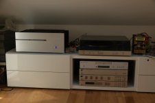
Finally, the new amp in its working "position" - in case someone wonders, that ugly thing on the right is an ACA, I maybe show a bit of that later 😎

Above being at 0.6 A of bias on one of the channels - I got both up to 0.95A and left it there - after a few hours of idling with the cover plate on I ended at 50 degrees heat sink temp behind the output mosfets, while the drain pins were around 70 degrees - I guess that's good enough...
A little bit cramped interior, with the speaker protection board on the right hand side of the PSU, and the soft start on the left hand side - put a divider and later on a cover around the soft start in order to avoid accidental touching of high voltage parts.
Finally, the face plate and the standby circuitry between PSU and back plate - needs some tidy up, later 😉 The standby circuit ensures that the whole story, including a remote driver for external speaker relais (to switch between amps) is ramped up in phases for around 30 secs, during which the blue on/off switch pulses nicely before going full on when ready to play - toys need to have some blue blinkin' light, don't they? 😀
In the end, this box is set up to be modular, to exchange amp boards later (F5 and Aleph-J planned), so there are quite some non-solder connections for ease of amp board replacement...only the inputs are solders as of now.
Finally, the new amp in its working "position" - in case someone wonders, that ugly thing on the right is an ACA, I maybe show a bit of that later 😎
Attachments


I have a silly question but …
Where do you get those big washers with the small holes in them to 'tie down' the TO-247 transistors? Are they spring or pressure washers?
I usually use transistor clips (like RS 504-0609 for example) for applying consistent device pressure or make up metal squares, but I can't find any "tension washers" or "wave washers" anywhere either
I have found some if the "Wave washers" at a company called MSC - they have a particular washer called #5 screw part number MSC 01587492 with ID of 0.143" (3.6mm) and OD of 0.282" (7.1mm) - deflection pressure of 7 lbs - would this be okay with a flat washer to cover the TO-247 transistor load surface?
Or is there another simple way of doing this?
Or is there another simple way of doing this?
Hi James, the washers that you see in my pics are actually from the back panel parts kit from the diyaudiostore.
I wouldn‘t overengineer this, I think I saw similar simple washers (that‘s what they are) in one of the hardware section of a local home improvement store recently. If the store and the HW section is large enough, then they should also have stock of such unusual washer sizes.
I wouldn‘t overengineer this, I think I saw similar simple washers (that‘s what they are) in one of the hardware section of a local home improvement store recently. If the store and the HW section is large enough, then they should also have stock of such unusual washer sizes.
Those are "penny washers"
Like these. A2 Stainless Steel Penny Repair Flat Washers M3 M4 M5 M6 M8 M10 M12 M14 M16 M20 | eBay
Like these. A2 Stainless Steel Penny Repair Flat Washers M3 M4 M5 M6 M8 M10 M12 M14 M16 M20 | eBay
- Home
- Amplifiers
- Pass Labs
- F6 Illustrated Build Guide