@ KampfKeks3000 amazing looking amps and hope you get the faulty components identified and replaced soon!!! 
So the heavy current peak could have killed the psu Filter caps?
That would explain the hum.
I dont have a scope... but maybe i can get one for testing.
We have to consider all possibilities and a scope check would be definitive.
Hard to see that any overload would harm the PSU cap's though. Depending on the current capability of the supply those parallel resistors might have been stressed. Perhaps even one of the diodes in one of the bridges has suffered.
With the offset at zero and bias set correctly check that both rails are equal value DC wise.
Just looking at the circuit and I think the amp should be DC stable without the input FET's in place. Why not remove the FET's, power up and having checked bias and offset (readjusting if needed) see if the hum is gone.
OK 🙂
It is sure to be an easy fix but a scope would make things much easier because we could then see what is going on. It takes all the guess work out.
It is sure to be an easy fix but a scope would make things much easier because we could then see what is going on. It takes all the guess work out.
Hi Mooly,
I have removed the jfets and checked the hum again.
It is worse than before.
Now I have measureable AC Voltage on the speaker terminals (~6V AC @ca.60Hz)...
But my Mains have 50Hz 230V.
@ Twitchie
Thank you 🙂
I hope i can find the fault soon, aswell
I have removed the jfets and checked the hum again.
It is worse than before.
Now I have measureable AC Voltage on the speaker terminals (~6V AC @ca.60Hz)...
But my Mains have 50Hz 230V.
@ Twitchie
Thank you 🙂
I hope i can find the fault soon, aswell
That sounds a bit odd... the frequency I mean. A DVM readout might be in error I suppose, particularly if it was a distorted kind of waveform. 100Hz is possible due to the full wave bridge rectifiers but not 60.
Would the signal transformer pick up stray hum with the FET's removed I wonder?
Without a scope we are guessing.
You could fit the FET's from the good channel as a test.
I'm thinking a bit deeper now... you say one of the 1000uF caps cooked. That means lots and lots of current has flowed through the gate of the FET concerned and also through the winding on the signal transformer. There is no other low impedance path. The 10k's isolate everything else so the power FET's and transformer took a hit.
I hate saying this when fault-finding 🙂 but I think you are coming down to a process of elimination.
Does the PSU also power another channel? If so and that is OK then the PSU is essentially proved OK.
Removing the input FET's might have been a bad call... can you swap them with known good ones.
After that its a case of output FET's or worst case the signal transformer. There is nothing else left.
I would start with the power supply. Disconnect everything from it and check for stable DC on all rails. Look also for any AC leakage.
You are right.
I will try to get a scope the next days.
Then I can measure the PSU properly.
Everything else is guessing.
Thanks 🙂
I will try to get a scope the next days.
Then I can measure the PSU properly.
Everything else is guessing.
Thanks 🙂
I hope the jensen transformer is okay....
That would be really really bad.
@ Mooly
No, the PSU is only for this channel.
And the transformer is far away from anything that could stray into it.
I will test another set of jfets after checking the PSU.
That would be really really bad.
@ Mooly
No, the PSU is only for this channel.
And the transformer is far away from anything that could stray into it.
I will test another set of jfets after checking the PSU.
OK and  the transformer is good.
Just thinking aloud now, uncharted territory.. with the JFET's removed could we not short out the two secondary windings on the transformer. Just a quick dab across each with wire.
The DC conditions would be unchanged and any resulting noise on the output would have to be a result of noise on the rails.
the transformer is good.Just thinking aloud now, uncharted territory.. with the JFET's removed could we not short out the two secondary windings on the transformer. Just a quick dab across each with wire.
The DC conditions would be unchanged and any resulting noise on the output would have to be a result of noise on the rails.
Yeah, I thought about that, too.
That should make the transformer quiet... if the noise is coming from it.
I Think i'll give it a try 😉
That should make the transformer quiet... if the noise is coming from it.
I Think i'll give it a try 😉
OK, worth a try.
Also if you are an experimenter then how about a series cap, resistor and speaker across each rail to see if there is excess ripple there. Have a listen and see if you hear excess noise.
Say 100 to 1000uF in series with a 100 ohm and a speaker. Once the cap is charged the resistor can be reduced right down.
Very interesting idea.
Maybe.. maybe...
I have to check if i can find a cheap speaker in my basement 😉
Maybe.. maybe...
I have to check if i can find a cheap speaker in my basement 😉
So.... a small update.
I tried so silence the transformer by putting a bridge from source to gate of one of the jfets (Soldering points on the pcb... jfets not in place).
The AC voltage on the speaker terminals was way lower, but still at 80mV AC (my DMM says AC but i can't tell the wave form excactly).
The hum in the speaker is still louder than with the jfets in place.
For the moment, the PSU is the main focus.
After that, i will replace the mosfets.
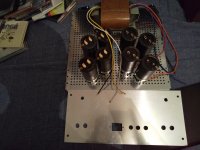
I am happy and appreciated that I could start to build F6 even don't really understanding electronics and audio.
I have 2 questions.
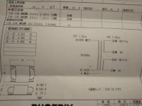
1) My transformer have ground line.
Should I need to connect transformer ground to chaiss or AC in my house?
Here in Japan don't have earth ground on house so may be no connect anywhere?
2) I have sic-sbd 650v 10A. Can I use them?
I have 2 questions.
1) My transformer have ground line.
Should I need to connect transformer ground to chaiss or AC in my house?
Here in Japan don't have earth ground on house so may be no connect anywhere?
2) I have sic-sbd 650v 10A. Can I use them?
Attachments
1) Transformer ground to chassi ground star.
Thank you Sov.
I will connect transformer earth ground line through cl60 to chaiss.
- Home
- Amplifiers
- Pass Labs
- F6 Illustrated Build Guide