I placed a new 2SK170 on the circuit to compare the voltages, I have exactly the same measurements.
(Polarity reversed)
(Polarity reversed)
Added corrections.
This is something you really should try.
Ok, I think I will. Can you explain the basic sonic comparison between this method, and the "degeneration" method. Seems like you like this method better than going with degeneration?
Thanks for any input,
Russellc
Repurposed a multichannel tank for a first watt build
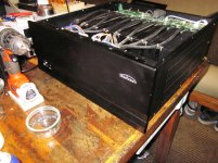
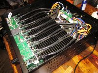
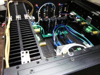
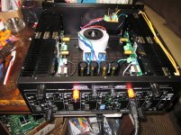
I bought a broken sherbourn 16 channel amp ($35 craigslist) and repurposed it for a F6. I was able to reuse the heatsinks by bolting them together and coupling with bits of aluminum. It's very heavy duty. I downloaded the gerber files for the amp board from pcbway and had them made at JLC.
I bought a broken sherbourn 16 channel amp ($35 craigslist) and repurposed it for a F6. I was able to reuse the heatsinks by bolting them together and coupling with bits of aluminum. It's very heavy duty. I downloaded the gerber files for the amp board from pcbway and had them made at JLC.
Attachments
Nice score!!!! nice repurposing.
Take out the 2nd row of heatsinks per side and save them for a different project. They won't be doing much of anything the way you've got it arranged and they'll be worth more for your next amp.
Take out the 2nd row of heatsinks per side and save them for a different project. They won't be doing much of anything the way you've got it arranged and they'll be worth more for your next amp.
Ok, I think I will. Can you explain the basic sonic comparison between this method, and the "degeneration" method. Seems like you like this method better than going with degeneration?
Thanks for any input,
Russellc
Yeah. I've gone back and forth a million times about the differing methods.
From a convenience point of view then degeneration does the job.
To get further improvements then going the way I described is best but it took quite a few measurements to get there.
Essentially you have an output stage that operates in the same manner as Aleph J, J2, ie more single ended but you don't get current limiting.
To really get the best from this, the preamp should be a low distortion design eg B1 R2 or Whammy etc. The idea is you want the modified F6 to sing on it's own, completely unadulterated by anything up stream.
Don't use Korg or ACP+ with this mod.
I have ordered 0.22ohm resistors for 2sk1530, now I am also interested in Picos magic.How different in sound
between 2k and 3.3k for R7,R8?
between 2k and 3.3k for R7,R8?
Further improvements to psrr which may or may not be an audible improvement.
Nevertheless it is a small measurable improvement.
Nevertheless it is a small measurable improvement.
Are your voltage references operating correctly?
Try measuring ripple across gate to source of each mosfet, see if they are all roughly the same value of ripple. Multimeter should be good enough.
If there is a problem there, then either the references are not doing there job, or there is a problem with the 1000uF caps.
Also, how much ripple do you have coming from each rail of the supply?
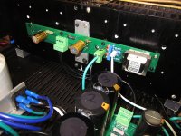
So after many hours of head scratching I started eliminating what I don't usually use.....(swapping out components) and this little F***er

was the cause of the hum.... It looks a quality item by a reputable manufacturer and measures bang on..
TIA for all who had a suggestion.
Could some one shed any light on why this was the cause of the hum issue.. I changed the other two omrite resiter too.
Hello,
here are the values measured on the PCB:
(I added the polarity, knowing that the negative of the voltmeter is placed on the Gate and the 0v.)
- G / S + 2,9v
- G / D - 2,9v
- 0v / S - 18,5v
- 0v / D - 24,5v
It is also useful to point out that the trimpots are at their lowest.
@ Super BQ: attached the photo of a JFET
On the photo it's GR, but I also have BL, the case is identical and the typography too.
These are genuine ones BL Grade: Click link as I don't want to post the hi-res photos that changes the viewing of this thread:
https://i.imgur.com/gTXYo1Y.jpg
https://i.imgur.com/wE46vrS.jpg
https://i.imgur.com/48tFIdi.jpg
Nothing is worse than working with parts that are 'not what they are'.
Excellent bloody work there.Could some one shed any light on why this was the cause of the hum issue.. I changed the other two omrite resiter too.
The feedback resistors are a critical component.
Get Vishay Dale CPF3.
@laverda,
Is it possible that the solder contact on the left side was loose. Based on the photo it might have been. Just a guess. Bill
Is it possible that the solder contact on the left side was loose. Based on the photo it might have been. Just a guess. Bill
It's wire wound and maybe picking up a stray magnetic field?
I could understand that if the PSU was adjacent the amp board but the hum was still present even when the power supply was off board, outside the case.
And why my regulated bench power supply produced no hum with these resistors.
cant get my head round it.
@laverda,
Is it possible that the solder contact on the left side was loose. Based on the photo it might have been. Just a guess. Bill
No I don't think so Bill as I reflowed every joint luckily there aren't that many.
- Home
- Amplifiers
- Pass Labs
- F6 Illustrated Build Guide