Kind of hard for me to get a grasp of the total picture of what has been done to fix the problem.
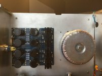
I don't like the untwisted secondary wires being so close to the Jensen transformers but maybe that has all been taken care of.
I don't like the untwisted secondary wires being so close to the Jensen transformers but maybe that has all been taken care of.
Just thinking out loud, but is it possible you helped the problem by removing the transformer from the case, but reintroduced it by running it (as in pic anyway) with the power supply no longer grounded through CL-60 to ground?
Maybe a wire (Zenmod don't forget my "24 hour wire" fiasco) from power supply ground to CL-60 to chassis ground? I haven't experimented with hum investigation via taking transformer out, but seems many I have seen do it here just temporarily removed it to check leaving power supply board mounted in chassis, with it's ground in tact.
Similarly, with a remote type power supply (or your lab supply) ground for PS would be secured....
Again, thinking out loud, you've got Pico looking and he knows this amp about as well as anyone, so you should be good.
I'm going to have to pull out my F6 boards and outputs for a little play time.
lots of good ideas have been shared here regarding F6 since my build, and later cannibalization of it...
Russellc
Thank you all very much 🙂
Great that you like it too.
@ 2 picoDumb
Never heard that phrase before 😀 Had to google a bit.
There's a character on the History channel's "The Curse of Oak Island" who uses that term when he locates an impressive relic. He's some kind of metal detection expert or has some such expertise. Oh, and those are very nice looking amps.
russellc
@Russellc
Thank you 🙂
Hahaha 😀😀
Nice to know.
Never heard of that show here in Germany, before.
Thank you 🙂
Hahaha 😀😀
Nice to know.
Never heard of that show here in Germany, before.
Help me R4 fire
Hello,
I need your help.
I recently launched into the construction of the PASS F6, I read this entire topic, and I therefore left on the basic diagram (first post) with the modifications made during the realizations:
- R11 / R12 121Ohms
- R7 / R8 3.3KOhms
- Z1 / Z2 6.0v (I did not find a 6.2v during my first order)
- JFET paired 7mA
- IRFP 240
I am counting on the 3x LED later.
Power supply:
1x https://www.diyaudio.com/forums/pow...e.html&usg=ALkJrhgSJ7KWiVGAaBHAUP8OazpYfr0ErA (60 000uF by chanel)
1x transfomer 2x18v 400VA
V- = -26.4v
GND = 0v
V+ = +26.4v
My problem:
During the first ignition I have R4 which is set to smoke after 10 seconds, I had no reading on R2 and I have 12v in HP output.
The 2 trimpots were set at half their value.
I checked my mass at the level of the MOSFETs OK, removed the 2 MOSFETs to continue, and resumed the setting of the BIAS, R2 smokes and one of the two JFETs is also smoked.😡
However, I checked the whole circuit 3 times, everything is correct, resistance value, diode mounted in the right direction, and the 2 channels have the same problem.
Do you have another avenue of research to suggest to me?
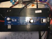
Quick update, both channels buzz/hum have lowered by this change, I just snipped exaxtly as in picture. The right channel is fine, as only noticeable with ear in horn. The left channel still has a prominent buzz. Could it be because I still have the led reversed in that left channel? (still have not found the courage to dismantle😉)
Anyway, thanks for the helpful tips so far.
Anyway, thanks for the helpful tips so far.
The left channel still has a prominent buzz. Could it be because I still have the led reversed in that left channel? .
Bloody oath
Last edited:
Hello,
Do you have another avenue of research to suggest to me?
Input Jfets 2SK170 and 2SJ74 in correct locations?
I had to look that up, haha! Ok, understood!Bloody oath
Yes, I also checked the locations before and after my problems.Input Jfets 2SK170 and 2SJ74 in correct locations?
Q3 = 2SJ170
Q4 = 2SJ74
I even checked if the circuit did not mislead me, but the drain of Q3 is fine on R7.
The 2SJ74 is out of order, I have other but not so well paired.
I forgot some precision, when I cut the power, the rail -26v is the one which discharged the fastest (almost instantaneously) normal.
And on my last test (without MOSFETs) I got 1.3v on R2.
Is BIAIS destructive to this tension?
Last edited:
If one rail discharged much faster than the other, it could be you have some bad caps in the rail that is discharging quickly.
Also check the bleed resistors etc also check solder joints on caps. If they are good then replace the caps.
I am assuming dc offset and bias adjustment is all good in the amp.
Also check the bleed resistors etc also check solder joints on caps. If they are good then replace the caps.
I am assuming dc offset and bias adjustment is all good in the amp.
Last edited:
The caps are MUNDORF gold, they are new.
The BIAS and the CC shift are not good (see my previous post 2 picoDumbs).
I especially thought that the fast discharge is related to the 2SJ74 HS
The BIAS and the CC shift are not good (see my previous post 2 picoDumbs).
I especially thought that the fast discharge is related to the 2SJ74 HS
I thought Id give the suggestion by 1543 a go. Removing the 'dirty end' 0v link on the PSU PCB tonight, sadly it didn't solve the hum issue...still the same.

eeerrrr
Last edited:
Thanks 2 picoDumbs, I'm struggling as I've never had this in 20 years of building (rather If I did I found an issue and fixed it) I'm sure its an issue with the PSU as the bench PSU doesn't produce the hum, that said the bench PSU is regulated so will have nice PSRR.
Swapped out the transformer.
Swapped out the PSU. Checked all solder joints..
Checked all the wiring is correct and twisted real nice.
Good grounding via CL60 and tried without.
Sig ground is good
Sig shorted or not...
Still humming nicely.
Thinking time....
Swapped out the transformer.
Swapped out the PSU. Checked all solder joints..
Checked all the wiring is correct and twisted real nice.
Good grounding via CL60 and tried without.
Sig ground is good
Sig shorted or not...
Still humming nicely.
Thinking time....
Last edited:
I especially thought that the fast discharge is related to the 2SJ74 HS
No way. Not that different.
Thanks 2 picoDumbs, I'm struggling as I've never had this in 20 years of building (rather If I did I found an issue and fixed it) I'm sure its an issue with the PSU as the bench PSU doesn't produce the hum, that said the bench PSU is regulated so will have nice PSRR.
Swapped out the transformer.
Swapped out the PSU. Checked all solder joints..
Checked all the wiring is correct and twisted real nice.
Good grounding via CL60 and tried without.
Sig ground is good
Sig shorted or not...
Still humming nicely.
Thinking time....
Are your voltage references operating correctly?
Try measuring ripple across gate to source of each mosfet, see if they are all roughly the same value of ripple. Multimeter should be good enough.
If there is a problem there, then either the references are not doing there job, or there is a problem with the 1000uF caps.
Also, how much ripple do you have coming from each rail of the supply?
Last edited:
- Home
- Amplifiers
- Pass Labs
- F6 Illustrated Build Guide