I measured the hum & noise on my Teaser-6 with a Fluke meter. Outputs connected to 8 ohm loads. Inputs connected to M-Audio AP-192 sound card with no signal.
left channel: 0.6mV AC RMS
right channel: 0.2mV AC RMS
I routinely rotate the transformers in FW product to set the noise levels
at the lowest equal value. My F6 proto came out a bit over 0.1 mV
😎
Papa,
When you say rotate, do you mean swap one out for another or twist the torroid on it's mounting bolt for minimum hum?
When you say rotate, do you mean swap one out for another or twist the torroid on it's mounting bolt for minimum hum?
Has anyone thought out the value of R1 to keep relative gain at 15db if using IRFP240's? I am prototyping this, but uncertain of a formula that can help.
My apologies if this has been mentioned already. I assume tweaking this and the degeneration resistors will get this working on point. I plan on using for source resistors 1R to start with the 10R Zen Pots.
I believe that R1 is the feedback resistor from output ? If so I'd leave it at 100R as this would still get us close to the orig 15 db gain。if you would like the actual exact formula it's somewhere earlier on this thread - I can look for it.
I routinely rotate the transformers in FW product to set the noise levels
at the lowest equal value. My F6 proto came out a bit over 0.1 mV
😎
I have been surprised a couple of times how much difference this can make. My builds tend to be in tighter quarters than what i have seen from the FW chassis.
I set both R13 and R14 at .025 ohms and spent a couple of days listening. I think the soundstage is both wider and deeper than with r13, R14 set to zero.I also appear to have more detail. Don't know if its me thinking I need to hear something different 😉 I am going to set R13 to .0125 , keeping R14 at .025and give a listen. Then I will reverse the two. In my system this resistance range is where I get the most stimulation to my ears. Resistors are 5W wirewounds
Best
Bob
Best
Bob
Papa,
When you say rotate, do you mean swap one out for another or twist the torroid on it's mounting bolt for minimum hum?
Twist.
😎
Twist.
😎
Attachments


That did the trick. After rotating only about 15 degrees both channels are somewhere between 0.1 and 0.2mV RMS. (The Fluke meter indicates 0.1mV with its leads shorted).
I routinely rotate the transformers in FW product to set the noise levels
at the lowest equal value. My F6 proto came out a bit over 0.1 mV
😎
wouldnt it be better to allow for the Toshiba jfets to be mounted either back to back, or side by side to allow thermal bonding either with grease/silver epoxy or one of EUVL's trick little heatsinks?
wouldnt it be better to allow for the Toshiba jfets to be mounted either back to back, or side by side to allow thermal bonding either with grease/silver epoxy or one of EUVL's trick little heatsinks?
Face to face (flat to flat) allows them to be zip-tied together for thermal tracking.
Face to face (flat to flat) allows them to be zip-tied together for thermal tracking.
sorry I mispoke, thats what I mean, face to face not back to back...doh! 🙄 for the thermal reasons you mention; but also Patrick's little heatsinks have them opposed, but side by side. neither of which can be used with the 2 layouts presented on this page
Patrick's heatsinks have them side by side so a pair of J74 could be used instead of a J109, on the same pad. For good thermal tracking face to face would be the most logical in this project.
Last edited:
F6
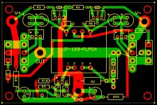
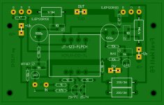
Tell me please, what would you like to tweak? I'll try to implement it.
Very nice. After a few tweaks I would definitely use it.
Tell me please, what would you like to tweak? I'll try to implement it.
Attachments


- Home
- Amplifiers
- Pass Labs
- F6 Amplifier