I am sorry for the lack of reply. I have not had the time to check diyaudio of late. However my computer is back up and I should be able to have the board to you in the next week or so.
Sorry for the delay
Alexis Shaw
Sorry for the delay
Alexis Shaw
Many thanks and welcome back, Alexis.
Take your time. We can still wait for the protection board.
Patrick
Take your time. We can still wait for the protection board.
Patrick
GB
Sorry for this non technical question :-
when is this GB open to public? I can only see 'potential' design case GB and the resistors GGB. I would very much like to get myself register for this GB, lest I get miss out.
Thanks
pmc
Sorry for this non technical question :-
when is this GB open to public? I can only see 'potential' design case GB and the resistors GGB. I would very much like to get myself register for this GB, lest I get miss out.
Thanks
pmc
You should register at the "potential" GB threads.
They will serve as default lists for later.
When I can formalise things depends on when I have a response from the Forum.
Till now I have not had a reply for 2.5 weeks.
Patrick
They will serve as default lists for later.
When I can formalise things depends on when I have a response from the Forum.
Till now I have not had a reply for 2.5 weeks.
Patrick
Someone asked me by PM about the PCBs.
Most of them are ready, pending review by Variac.
After that, we shall prototype a limited number so that they can be functionally tested for bugs.
If the PCBs are error free, and I expect them to be, then the forum would order in quantity and make them available through the online shop.
At the same time, we shall publish the standard circuit and the bill of materials.
When that might be depends more on the forum than on me, as my part of the work is basically ready.
The PCB will support a minimum of 6 different configurations according to my current list. Except for the standard configuration, which I have built and tested years ago, they will only be published (one after another) after each configuration has been built and tested. So it will be a long journey still to come. Most of the configurations involves minor component changes or addition, so you would not have to have 12 PCBs to go through all the variants.
Patrick
So I finally heard from Variac.
It appears my emails he never received.
So I need to figure out a new way to communicate with him.
In the meantime, I am looking for 3 volunteers (one for each continent) to help me with the case GB.
This will relieve our workload a lot, as we then only deal with 3 persons rather than 25.
The names I have in mind would be Greg or Fred, Uwe, and John.
If you are willing to help me, please send me a email via the forum.
I shall then give you more details.
After that, I shall release some photos, detail specifications as well as estimated price, here.
Thanks in advance,
Patrick
So I finally heard from Variac.
The names I have in mind would be Greg or Fred, Uwe, and John.
If you are willing to help me, please send me a email via the forum.
I shall then give you more details.
Thanks in advance,
Patrick
Hi Patrick,
you got an email.
BR, Uwe
Patrick,
If after you release the pictures there is more interest, why don't we check the possibility to have cases produced locally, like finding one manufacturer in USA, one in Europe and one in Asia. This will cut a lot of shipment costs.
D.
If after you release the pictures there is more interest, why don't we check the possibility to have cases produced locally, like finding one manufacturer in USA, one in Europe and one in Asia. This will cut a lot of shipment costs.
D.
This is the least that I can do for the group, PM follows.The names I have in mind would be Greg or Fred, Uwe, and John.
> If after you release the pictures there is more interest, why don't we check the possibility to have cases produced locally, like finding one manufacturer in USA, one in Europe and one in Asia. This will cut a lot of shipment costs.
a) There is assurance of quality.
b) There is no control of the intellectual properties of the drawings.
c) It will probably be more expensive than us including shipment.
We thought about that and decided not to, in the end.
I did not see a flood of subscribers after the 25, so for me it was a good number, for this year.
😉
Patrick
Many thanks to the volunteers.
You will receive a email something during the course of today.
Patrick
You will receive a email something during the course of today.
Patrick
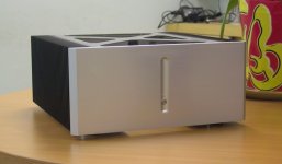
Here I release the first photos and details of the case. More to come later when I have time.
-- Overall dimensions are approximately 350 (W) x 370 (D) x 170mm (H).
-- 2 Conrad MF35-151 heatsinks.
-- 15mm thick AL6061 CNC milled front panel, with cut-outs on the rear surface for the protection PCB. Brushed and matt anodised.
-- 303 SST push button; 3mm dual colour (Red/Blue) LED.
-- the Proto now shows a 2mm SST top plate laser cut, with 0.8mm diameter wire mesh, 3mm grid, underneath (not yet shown); however we intend to replace this with 3mm thick aluminium 6063 with CNC drilled 3mm perforations to make the "X".
-- 96mm standard kitchen size SST handle (so that you can choose other ones to your taste).
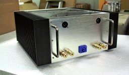
-- Rear panel 3mm AL6063 (to be) matt anodised is detachable and NOT part of the structure, to allow customised engraved rear panels from Schaeffer, etc.
-- 303 SST feet
The other features (transformer vibration isolation from case) will be explained later together with the photos.
Hope it meets your expectations,
Patrick
PS The rear panel has a slight error in that one XLR is turned 90°. This will be corrected in volume production.
.
-- Overall dimensions are approximately 350 (W) x 370 (D) x 170mm (H).
-- 2 Conrad MF35-151 heatsinks.
-- 15mm thick AL6061 CNC milled front panel, with cut-outs on the rear surface for the protection PCB. Brushed and matt anodised.
-- 303 SST push button; 3mm dual colour (Red/Blue) LED.
-- the Proto now shows a 2mm SST top plate laser cut, with 0.8mm diameter wire mesh, 3mm grid, underneath (not yet shown); however we intend to replace this with 3mm thick aluminium 6063 with CNC drilled 3mm perforations to make the "X".
-- 96mm standard kitchen size SST handle (so that you can choose other ones to your taste).
-- Rear panel 3mm AL6063 (to be) matt anodised is detachable and NOT part of the structure, to allow customised engraved rear panels from Schaeffer, etc.
-- 303 SST feet
The other features (transformer vibration isolation from case) will be explained later together with the photos.
Hope it meets your expectations,
Patrick
PS The rear panel has a slight error in that one XLR is turned 90°. This will be corrected in volume production.
.
Attachments
A couple more details :
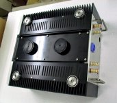
One of the major concern at the beginning was plate vibration of the bottom plate. So initially the case was designed with a 8mm bottom plate in mind. This, however, is not only heavy (to ship) and expensive, but also still not rigid enough with 2 big masses (toroids) sitting in the middle.
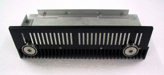
So instead, they are now placed on a central cradle which is folded into a U-channel from 3mm AL 6063, and then machined to the required dimensions. Folding in a U gives it tremendously more stiffness, increasing the natural frequency significantly.
To improve the dynamical behaviour even further, two extra Aluminium feet are placed directly below the centre of the transformers to support their weights. This will also allow the transformer to be dynamically decoupled from the rest of the case. Details of how that might be done would be included in the assembly procedures of the case.
Similarly, the rear bracket (black, hidden behind the rear panel which is purely decorative) is also folded from 3mm 6063 AL into an open-top box . The only "thin" plate left in the case is the top plate, but this is unlikely to receive much acoustic excitation as it is near 50% perforated. Hence little pressure difference can exist between top & bottom surfaces.
The same also applies to the two bottom side covers. Their only function is to cover the case entirely for electrical safety.
Patrick
One of the major concern at the beginning was plate vibration of the bottom plate. So initially the case was designed with a 8mm bottom plate in mind. This, however, is not only heavy (to ship) and expensive, but also still not rigid enough with 2 big masses (toroids) sitting in the middle.
So instead, they are now placed on a central cradle which is folded into a U-channel from 3mm AL 6063, and then machined to the required dimensions. Folding in a U gives it tremendously more stiffness, increasing the natural frequency significantly.
To improve the dynamical behaviour even further, two extra Aluminium feet are placed directly below the centre of the transformers to support their weights. This will also allow the transformer to be dynamically decoupled from the rest of the case. Details of how that might be done would be included in the assembly procedures of the case.
Similarly, the rear bracket (black, hidden behind the rear panel which is purely decorative) is also folded from 3mm 6063 AL into an open-top box . The only "thin" plate left in the case is the top plate, but this is unlikely to receive much acoustic excitation as it is near 50% perforated. Hence little pressure difference can exist between top & bottom surfaces.
The same also applies to the two bottom side covers. Their only function is to cover the case entirely for electrical safety.
Patrick
Attachments
Each of the heat sinks has 2 SST feet, and the bottom side cover is directly bolted on using countersunk screws, so that the screw head is not visible from the side. This however puts extra demand on machining tolerances of all holes.
(I hate seeing screw heads sticking out from a case. It is only for cheap cases where they use long slots and button headed screws extensively to compensate for poor part tolerances.)
The PSU C-Reg-C has dual bridge and no common ground until they met at the star point right in the centre of the amplifier PCB. This allows the placement of the PSU capacitors to be as close to this high-bandwidth amplifier PCB as possible (near the "cool" ends of the heat sink).
So as such, each channel of the F5X can be finish assembled and tested on its own, with the PSU caps already in their final position, before it is finally wired up in the case.
Patrick
Attachments
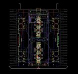
The next picture shows the layout of the major components within the case, including the amplifier boards (at the thermally optimised position), PSU caps, toroidal transformers, rectifiers, regulator PCBs and heat sinks, Aus PSU, etc.
The control and protection board is hidden in the front panel and hence not visible.
Patrick
The control and protection board is hidden in the front panel and hence not visible.
Patrick
Attachments
Hi all,
the PSU mosFETs arrived in Scotland.
At first Delivery (25th March) I was not in to sign for the packet.
Since then the packet has gone back either to the local post office or to the local delivery depot. It has gone missing in that journey and cannot be traced.
Despite many promises the packet has not been re-delivered nor found.
I have raised a complaint re our "lost/missing" Special Delivery packet.
Zhou (the Sender) will have to raise a compensation claim when he gets back to Singapore, next week.
Sorry for the delays
Last edited:
Thank you for the update, Andrew.
As mentioned before, the FETs have been sent by insured post (6 USD extra).
Money well invested in this case, unfortunately.
Patrick
As mentioned before, the FETs have been sent by insured post (6 USD extra).
Money well invested in this case, unfortunately.
Patrick
- Home
- Amplifiers
- Pass Labs
- F5X -- the EUVL Approach