
15.000uf each capacitor
Yes. 🙂
You mention you have the diyAudio PSU circuit boards, so there are 8 positions for each board.
Well, I have studied the shopping list and have unclear least a couple of questions about the transistors.
I have to buy 2sk170 bl / 2sj4bl. 2sk170bl have enough leftover from other projects, id of 9-10 mA. This is a good range ?. I guess I have to buy 2sj4bl close to that range, but the nearby ?. I read somewhere 0.2mA is good.
On the shopping list appears:
"Q1 (Q3) = 2SK170BL
*Q2, (Q4) = 2SJ74BL "
Where is (Q3) and (Q4) ?. How many are in total?
There are two types of mosfet to put IRFP9240, FQA12P20, what is better? Are there differences in the sound? They must be well matched?
I searched through the 400 pages of thread F5t build and I have found nothing about this.
2SC4793 / 2SA1837 must be matched?
No doubt the matched component is the hardest to get and I guess there is one secret of this amplifier.
In the photo at the beginning of this thread there are sinks in r8 / r9 and Q8 / Q9. I can understand sinks transistors but because the resistors?
r7 / r10 to refill?
and now finally ...😀... I have to fill Q1.1 / Q2.1?
6l6 Thanks for your help !
I have to buy 2sk170 bl / 2sj4bl. 2sk170bl have enough leftover from other projects, id of 9-10 mA. This is a good range ?.
Yes, wonderful!
Good plan.I guess I have to buy 2sj4bl close to that range, but the nearby ?. I read somewhere 0.2mA is good.
Probably means Q1.1, Q2.1On the shopping list appears:
"Q1 (Q3) = 2SK170BL
*Q2, (Q4) = 2SJ74BL "
Where is (Q3) and (Q4) ?. How many are in total?
You only need 1 Jfet pair per channel
Use the ones you can get more easily. No difference in performance or sound.There are two types of mosfet to put IRFP9240, FQA12P20, what is better? Are there differences in the sound?
Yes.They must be well matched?
No.2SC4793 / 2SA1837 must be matched?
The precision resistors obtained in a group buy required heatsinks for the dissipation. Use normal 3W resistors in that position and have no worries.In the photo at the beginning of this thread there are sinks in r8 / r9 and Q8 / Q9. I can understand sinks transistors but because the resistors?
No. That's there if you are going to have many output devices, bigger than an F5Tv3.I have to fill Q1.1 / Q2.1?
OOOOK! 🙂
Looking sinks have two options, one far more expensive than another.
1- 300 X 165mm 40X temperature coefficient 0.31 ° C / W. A sink for each output boards. Sinks totally 4
2-350 X 48 X 151mm temperature coefficient 0.21 ° C / W. A sink for each output boards. Sinks totally 4
Prefer option 1 by price and do not know whether it is sufficient dissipation. In Sevilla have in summer, at least 30 degrees inside the houses have to connect the cold climate.
Go with option 2! Sevilla is quite hot and you can never have too much heatsink!
 yes, very hot in summer. It is essential cold climate. I will then go through the MF35 conradheatsinks.
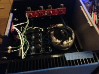
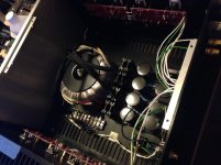
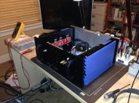
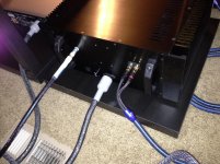
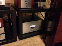
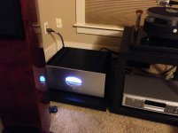
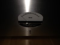
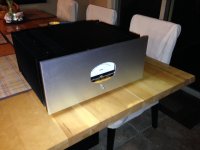
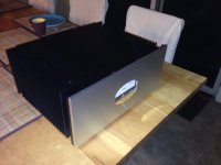
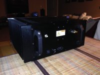
I finished my F5T. With 28V DC I have about 65W into 6 Ohm on my monoblocks. Please see attached pictures.
Great help from 6L6!!!! Thank you 6L6 a lot.
Still waiting for the front “half-moon shape” brass pieces, but it is cosmetics…
It is sounding very good to me. I tried to adjust P3 to min distortion and I used some local audio repair shop since I do not have distortion or spectrum analyzer.
My Bias is set to 1A (470mV) and MOSFETs are Toshiba 2SJ201 / 2SK1530.
Attachments

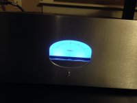
Fantastic!! It looks wonderful!
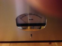
The meter looks great, very nicely done.
Congratulations on a successful, and very beautiful project!
😀 😀 😀
The meter looks great, very nicely done.
Congratulations on a successful, and very beautiful project!
😀 😀 😀
Also, would like to thank Spencer from FET Audio | Hi-End Audio Projects for quality parts supply and setup help.
Alex...
Congratulation on your build.
Im looking also on same build with the Bias meter in front.
Im sending you PM.
Regards...
Congratulation on your build.
Im looking also on same build with the Bias meter in front.
Im sending you PM.
Regards...


I'm done with my F5T final touches and P3 adjustment. It sounds fantastic now and it is hard to describe that in writing. I acquired HP 339A analyzer and with tremendous help from 6L6 got very nice/transparent/detailed/fresh/lifelike sound. Thank you a lot 6L6. Accomplishment with such project will be impossible without your knowledge and experience.
Attachments

Hi, I've ridden my f5turbo ... it sounds great !.
The dc offset is within 4mv variation. The bias is now at 310 mv in both channels. A channel the difference between N and P channel is 2 mv but on the other channel is 20mV.
In both channels the voltage of the power supply is 33V with a variation of 0.3 v.
Is it acceptable 20mV difference between N and P ?. I used the same values of resistance in the two channels of 1% tolerance and all transistors are matched
If I have 20mV of difference between N and P, what is the value I have to make reference to establish the bias ?.
Thanks for the invaluable help.
the output Vgs sets the output device current. This Vgs depends on each device, all are different.
The jFet supplies a voltage that drives the Vgs+Vrs
If the Rs are accurately matched before assembly and there is no degradation due to soldering then when output offset is zero the upper and lower Id are identical and the upper and lower Vrs are identical.
The only variation left is the Vgs.
you can get the same Id (zero output offset) with different Vgs.
That is normal.
2mVgs difference between N & P is exceptionally low. I suspect few Builders find values as close as this
20mV difference seems more normal.
the output Vgs sets the output device current. This Vgs depends on each device, all are different.
The jFet supplies a voltage that drives the Vgs+Vrs
If the Rs are accurately matched before assembly and there is no degradation due to soldering then when output offset is zero the upper and lower Id are identical and the upper and lower Vrs are identical.
The only variation left is the Vgs.
you can get the same Id (zero output offset) with different Vgs.
That is normal.
2mVgs difference between N & P is exceptionally low. I suspect few Builders find values as close as this
20mV difference seems more normal.
Thank you very much for your answer !, so if I have 20 mv difference between n and p, and want to establish a bias 375mv, which is my number ?. while a channel reaches 375mv, the other is 355mv and sinks are two degrees colder.
The difference between the N and P is normal and inconsequential.
Set bias until you have one heatsink at 55C max, Transistors pin 2 max 65C.
Or set bias until one side is 375mA and be done. Listen to music, don't worry about the amp - it's complete! 🙂
Set bias until you have one heatsink at 55C max, Transistors pin 2 max 65C.
Or set bias until one side is 375mA and be done. Listen to music, don't worry about the amp - it's complete! 🙂
- Home
- Amplifiers
- Pass Labs
- F5Turbo Illustrated Build Guide