if your two Rs are identical and your two Id are identical you can't get Vrs error of 20mV
What tolerance did you accept when selecting your Rs values?
Did you attempt to measure them?
This part of the build !
What tolerance did you accept when selecting your Rs values?
Did you attempt to measure them?
This part of the build !
if your two Rs are identical and your two Id are identical you can't get Vrs error of 20mV
What tolerance did you accept when selecting your Rs values?
Did you attempt to measure them?
This part of the build !
No, I have not measured the resistance with pinpoint accuracy only with the tester to check the value. I bought PRP and mills with 1% tolerance. MOSFET and JFETs are paired.
In any case it is not important whether I'll finish the chassis. Thank you!
I need to disable few output pairs on my Turbo v3 in order to handle the heat dissipation on my heatsink better. The heat sinks are not able to handle 4 Pairs on each channel. Till I find a solution to solve the heat dissipation can I simply lift the gate stopper resistors off the PCB and prevent any gate voltage on the selected output pairs and in turn prevent those selected power mosfets from turning on?
I read that this cannot be done on VFETS but Mosfets are OK. Am I correct?
Please advice.
Cheers.
I read that this cannot be done on VFETS but Mosfets are OK. Am I correct?
Please advice.
Cheers.
MOSFETs such as IRF240 etc. have a small leakage current through the gate that must flow. If the gate is open, the leakage current will charge it's own gate up and turn on the MOSFET after a short time. I would take the gate to Gnd or the source but removing it is probably wise. 😀
I would take the gate to Gnd or the source but removing it is probably wise. 😀
Are you saying disconnecting gate is not a great idea and therefore should remove the MOSFET completely from the board? I am trying to avoid this as I need to unmount the PCB and the MOSFETs to do this, which is messy.
Cheers.
Anil, consider removing both the gate and source resistors. This will help with leakage and the front end has a little less capacitance to deal with. Floating gates is never a good idea.
Gate to ground will basically destroy the MOSFET as the source is at full rail voltage and resulting Vgs is beyond the permissible device limit. You could take it to source by shorting out the pins above the PCB, and removing the gate resistor as well.
Alternatively, try lowering the bias a touch. If you post some numbers it would be nice. Not totally familiar with your project.
Sangram,Anil, consider removing both the gate and source resistors. This will help with leakage and the front end has a little less capacitance to deal with. Floating gates is never a good idea.
Gate to ground will basically destroy the MOSFET as the source is at full rail voltage and resulting Vgs is beyond the permissible device limit. You could take it to source by shorting out the pins above the PCB, and removing the gate resistor as well.
Alternatively, try lowering the bias a touch. If you post some numbers it would be nice. Not totally familiar with your project.
This is an old build. More than 1.5 years I guess. I have been running at lower bias to allow for the heatsink to keep the Mosfets from drifting due to increasing temp. The reason I want to disable 2 pairs on each channel is to push each pair to work at their designed bias levels and not lot lower. This is a massive heatsink setup, and yet the Turbo V3 pushes it beyond the limit. I need to mount some low noise fans to force air cooling. Till such time wanted to get these disabled.
Cheers.
Just removing the source resistor will be sufficient to disable the MOSFET. To stop it interacting with any other part of the circuit, removing the gate resistor as well will take it completely out of circuit, though that might not be necessary.
Yes, this is true. I was not thinking of the F5 configuration. Sorry....Gate to ground will basically destroy the MOSFET as the source is at full rail voltage and resulting Vgs is beyond the permissible device limit. You could take it to source by shorting out the pins above the PCB, and removing the gate resistor as well.
But, it is a bad idea to leave a gate floating. 😉
Transformer Question New Build
Hi All
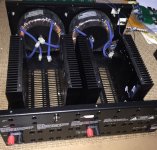
I have 2 old 16 chl Crestron Amps, built by ATI, and as I have no use for such a beast, and it's not really that valuable anymore (Check ebay) I have decided to try and re-purpose them into something better.
All of the components and chassis are very nicely made, and seem well suited to become a F5T v2, or possibly even v3's. (Have a look at the re-configured chassis below) Although only 4U, they are a bit deeper than the chassis offered on the DIYaudio store, and the heat sinks configured in this way seem reasonable.
The only concern is the transformers, they have 4 center tapped secondaries, as the 2 transformers then had 8 secondaries combined, to power the 8 stereo pairs (= 16 channels) of the original amp.
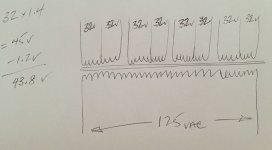
According to the ATI website, these transformers are built in house, and I don't seem to be able to get much information on them, other than measuring them myself. The Secondaries are 32-0-32, and the original power supply (Measured from amp before gutting) produces +/- 40VDC.
The TOTAL VA rating of the transformer must certainly be capable of powering the F5T, certainly with 2 in the chassis, and I have room in there for 2 x DIYaudio PSU's, so would be a dual mono in one chassis.
....but to get the required VA from these transformers, I would like to connect the 4 secondaries in parallel, so that I'm using the total VA capabilities of the transformer.
Can I do that ?
Does anybody here have any experience with such a concept.
If I cannot do this I don't think these transformers would be suitable.
I have attached a pic of the chassis stripped out of the original components and ready for some new guts, re using these transformers would be prefferable, and VERY cost friendly.
Hi All
I have 2 old 16 chl Crestron Amps, built by ATI, and as I have no use for such a beast, and it's not really that valuable anymore (Check ebay) I have decided to try and re-purpose them into something better.
All of the components and chassis are very nicely made, and seem well suited to become a F5T v2, or possibly even v3's. (Have a look at the re-configured chassis below) Although only 4U, they are a bit deeper than the chassis offered on the DIYaudio store, and the heat sinks configured in this way seem reasonable.
The only concern is the transformers, they have 4 center tapped secondaries, as the 2 transformers then had 8 secondaries combined, to power the 8 stereo pairs (= 16 channels) of the original amp.
According to the ATI website, these transformers are built in house, and I don't seem to be able to get much information on them, other than measuring them myself. The Secondaries are 32-0-32, and the original power supply (Measured from amp before gutting) produces +/- 40VDC.
The TOTAL VA rating of the transformer must certainly be capable of powering the F5T, certainly with 2 in the chassis, and I have room in there for 2 x DIYaudio PSU's, so would be a dual mono in one chassis.
....but to get the required VA from these transformers, I would like to connect the 4 secondaries in parallel, so that I'm using the total VA capabilities of the transformer.
Can I do that ?
Does anybody here have any experience with such a concept.
If I cannot do this I don't think these transformers would be suitable.
I have attached a pic of the chassis stripped out of the original components and ready for some new guts, re using these transformers would be prefferable, and VERY cost friendly.
Attachments
Last edited:
Are there 3 or 4 connected wires in each plug at the end of the blue cables? Multiple CT present a problem.
Does the transformer have dual (universal) primaries?
Those heatsinks are small, you will likely need a fan. Probably something low-speed will be fine, but those inside the chassis will not be super efficient.
Does the transformer have dual (universal) primaries?
Those heatsinks are small, you will likely need a fan. Probably something low-speed will be fine, but those inside the chassis will not be super efficient.
There are 4 connected wires on each plug, but I seem to remember that 2 are shorted together. I'll double check when I get home.
Here is a link the the ATI web page that gives some info about the transformer and chassis.
ATI Amplifier Technologies About
Would the alternative to be a full wave rectifier bridge at the end of each connector, and then parallel the rectified +/- DC power, before the CRC filter ?
The chassis is 400 mm deep, each heat sink is approx 190mm, so for some quick research of the 4U and 5U chassis offered on the DIYaudio Store, I think the overall amount of surface and material is somewhere between the 4U and 5U, Yes the center 2 sinks would be less efficient, but I can drill some new holes to mount the sinks further apart, and try and create more space between them if this project seems fisable. I just used some existing holes to breadboard the concept.
I can also create openings in the top and bottom cover to allow more convection, as in my Madrigal Proceed 5 Chl Amp.
I would mount the FE board on the rear panel, next to the input RCA, and O/P Binding Post, and there is enough space between the transformers and the heat sinks for the DIAAudio PSU Diode boards, and space between the sinks for the PSU Cap Boards.
Attachments
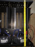
If there is 4 wires, and 2 were shorted in the original amp, that means (hopefully) that is actually a bunch of equal secondaries.
Can you use the continuity tester of you DMM and see if the plugs are in fact two separate winding? A CT will have continuity to both ends of the winding, but two winding will be separate from each other.
Can you use the continuity tester of you DMM and see if the plugs are in fact two separate winding? A CT will have continuity to both ends of the winding, but two winding will be separate from each other.
understood,
I'll check tonight.
Also I will accurately measure the heatsink dimensions and weight, and can more accurately compare them to what others have used here on the forum.
Thank you very much for the guidance, re using these chassis (and a lot of nice components from the PSU's and Amp PCB's ) will allow me to build a couple of nice amps for a few hundred dollars worth of DIYaudio PCB's and some MosFets.
Last edited:
I think you have the makings of a very nice amp. Worst case is you need new transformers and a fan. Best case, everything works as-is.
Either way, it seems pretty good. 🙂
Either way, it seems pretty good. 🙂
I have had a chance to measure the continuity of the secondary coils of the transformer.
The 4 wires coming from one lead are 2 independent loops.
This appears to be similiar to the Antek transformer <IMG_2282.jpg> in your post #192 on page one of this thread. http://origin.dastatic.com/forums/gallery/data/500/IMG_2282.jpg
On the PCB's of this donor amp, in the power supply section, two of the wires are are connected to the same point.
So looking at the build thread and, the PSU v3 boards, these transformers seem to be suitable, so the original question remains ...
Can I connect the 8 secondaries in Parallel, to use the entire VA capabilities of these transformers ?
Last edited:
The Heat Sinks from the ATI Donor amp, from post #151 of this thread, are;
190mm x 160mm x 35 mm, @ 1324 grams
7 5/8" x 6 1/8" x 1 3/8", @ 214.7 oz
To fairly compare these to the DIYaudio Store offerings can anybody supply the exact dimensions and weight of the Deluxe 4U and Deluxe 5U chassis heat sinks ?
Looking at the images from the Web Store it appears that the 4U is a single full length heatsink, so my numbers would then be doubled to make an equal comparison that that heat sink.
My current thinking is to install one output board (2 x Mosfets, 2 x Diodes ) per heatsink, and place the FE board on the rear of the chassis between the RCA I/P and Binding Post O/P.
connect each secondary to own dedicated Graetz bridge , then parallel what you intend
only in that way you can prevent current mess , which is result of (always existing) even slightest mismatch between secondaries
only bifilar (and more ... tri... etc.) windings are equal enough for paralleling
only in that way you can prevent current mess , which is result of (always existing) even slightest mismatch between secondaries
only bifilar (and more ... tri... etc.) windings are equal enough for paralleling
Hi Zen Mod
Apparently according to the manufacturer of the transformers they are Bifilar,
ATI Amplifier Technologies About
But I did also consider the possibility of rectifing first, then paralleling the DC, before the CRC filter. as mentioned in post # 153 above
Apparently according to the manufacturer of the transformers they are Bifilar,
ATI Amplifier Technologies About
But I did also consider the possibility of rectifing first, then paralleling the DC, before the CRC filter. as mentioned in post # 153 above
- Home
- Amplifiers
- Pass Labs
- F5Turbo Illustrated Build Guide