Thermistor resistance has variation with temperature and voltage. they are not very accurate and their absolute value is not of much concern in this circuit. You can live with a fairly large variation because the trimmer is used to set the final, total drain resistance for the input pair. In operation they will be at only a kilo-ohm or so anyway because of the elevated temperatures.

I have a technical question.
Does the F5 Turbo V2 benefit if I use two pairs ( in parallel) JFets (2SK170BL & 2SJ74BL)?
Yes, I talk about well matched J-Fets.
I do have some extra J-Fets but only would parallel it (piggy back) if there is a real benefit, otherwise I save it for a future project.
Thank you!
Does the F5 Turbo V2 benefit if I use two pairs ( in parallel) JFets (2SK170BL & 2SJ74BL)?
Yes, I talk about well matched J-Fets.
I do have some extra J-Fets but only would parallel it (piggy back) if there is a real benefit, otherwise I save it for a future project.
Thank you!
Thanks for your fast reply!
I will use only 2 pairs per channel (with the diodes).
Based on your answer there is no benefit to parallel the JFets.
I will use only 2 pairs per channel (with the diodes).
Based on your answer there is no benefit to parallel the JFets.
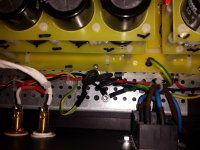
I finally solved my hum problem. My self designed PSU has a rather thick slab of copper as central ground. Both the grounds of the left and right channel pcb's were directly connected to that. Since the grounds of most source outputs are also connected to eachother, this created my ground loop. I solved it by giving the left and right channel and the PSU each its own ground lift (3 thermistor in total, see attachment). But now I wonder if there are any sonic disadvantages to doing it this way? I have the impression the amp sounds less balanced, less precise, with definitely more sibilance. Could this be?
Attachments
Last edited:
CL60 used here has cold resistance 10 ohms, sorry didn't look at the picture first.
Added resistance should be about 0.1 - 0.5 ohms. And preferably followed by some additional reservoirs after.
I have the impression the amp sounds less balanced, less precise, with definitely more sibilance. Could this be?
Because of the grounding? No.
Supply impedance is a little higher but shouldn't be anything significant, typically will be swamped by the source resistance connected to the MOSFETs.
CL60 used here has cold resistance 10 ohms, sorry didn't look at the picture first.
Added resistance should be about 0.1 - 0.5 ohms. And preferably followed by some additional reservoirs after.
So if I understand you correctly the best I can do is reconnect the left and right pcb ground to my PSU ground plate through a 0.1 - 0.5 ohm resistor? I have a couple Panasonic ERX-3SJ 0.47 ohm left over from the CRC filters; will those do?
Last edited:
Is this an all balanced setup, or mixed source and amp bal/unbal, or completely unbalanced everything? Also important to know how ground and chassis are connected in each of the components. Basically you are opening a can of worms. If everything is done properly (which is rarely the case), there shouldn't be any ground loop or hum.I finally solved my hum problem. My self designed PSU has a rather thick slab of copper as central ground. Both the grounds of the left and right channel pcb's were directly connected to that. Since the grounds of most source outputs are also connected to eachother, this created my ground loop. I solved it by giving the left and right channel and the PSU each its own ground lift (3 thermistor in total, see attachment). But now I wonder if there are any sonic disadvantages to doing it this way? I have the impression the amp sounds less balanced, less precise, with definitely more sibilance. Could this be?
Unbalanced everthing. Build with DIYAudio PCB's and kits according to this Build Guide, except for the (single) PSU of my own design for both left and right. As I wrote that has a rather thick copper slab as central ground between plus and minus, so very low impedance. The left and right Amp PCB grounds were directly connected to it, hence the ground loop.
I have now reconnected those PCB grounds to the central PSU ground through 0.47 ohm resistors (see attachment): no hum. I also reinstalled the rectifier bridge. And according to my ears there are for sure sonic improvements in comparison to my earlier setup with 3 thermistors!
I have now reconnected those PCB grounds to the central PSU ground through 0.47 ohm resistors (see attachment): no hum. I also reinstalled the rectifier bridge. And according to my ears there are for sure sonic improvements in comparison to my earlier setup with 3 thermistors!
Attachments

A question(s) for the learned please.
Just starting to put parts together for an F5 Turbo monoblock pair.
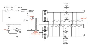
Have I interpreted the PSU correctly per my changes to Nelson's published schema for 120v to a 220v/230v primary with 36-0-36 secondary version?
Does the ground loop isolation diode bridge voltage spec need to be increased as well? I am assuming not as it's purpose if I understand correctly is not to ever handle the AC primary side voltage.
At 1000VA, is the original 4A SLOW 3AG still reasonable?
Just starting to put parts together for an F5 Turbo monoblock pair.
Have I interpreted the PSU correctly per my changes to Nelson's published schema for 120v to a 220v/230v primary with 36-0-36 secondary version?
Does the ground loop isolation diode bridge voltage spec need to be increased as well? I am assuming not as it's purpose if I understand correctly is not to ever handle the AC primary side voltage.
At 1000VA, is the original 4A SLOW 3AG still reasonable?
Attachments
- Home
- Amplifiers
- Pass Labs
- F5Turbo Illustrated Build Guide