As much as I love the look of these, I was wondering if a pair of ACA cases could be repurposed instead with the mosfets fitted on extension wires of a few inches from heatsink to the board mounted on the base of the case? That's then 1 heatsink per mosfet. I ask of course because I am a cheapskate and already have a pair of ACA cases. This also assumes that Nelson will offer boards only with a BOM when the time comes🙂 ?
ACA sinks might be a bit on the small side, but why not? Worth a try. Someone more knowledgeable about the thermal load will be able to tell you with math. The Redux doesn't burn up because of the fan. With ACA case monos, you may still need some moving air.
@captain pugwash - With a pair of monoblocks...
A pair of ACA heatsinks <=> 2U / 400 heatsink.
Nelson demonstrates using the 2U/300 in his article on the F5m at a recommended bias current. So, from a total dissipation standpoint, you'd likely be okay depending on what you're trying to accomplish.
What I can't comment on is if having the thermal tracking of each MOSFET so different would have an impact or any other cautions you may need to take when mounting each of the MOSFETs on different heatsinks across the chassis from each other vs. heatsinks butting up against one another or on the same 'porcupine' / 'hedgehog' sink. I'm also not sure what precautions you may need to take re: stability with the use of the flywires based on how long they might be. Move the source resistors closer? Not sure.
tl;dr - I think it'd be neato.
FWIW - I'm in the process of putting an F5m (not the Redux) in a 2U / 400. My Reduxeseseseses are AWESOME, but my brother broke one... This is why I can't have nice things. 🙂
Edited for content re: F5m vs. F5m Redux and some added humor.
The F5M pdf mentions the "Diss 2U" case as suitable and this has 300x80x40mm sinks, the ACA case has 200x80x40mm sinks so with only one mosfet per sink I assumed this would be fine. I was mostly unsure about extension wires on the mosfets as I've never seen this done before.ACA sinks might be a bit on the small side

Duh, I posted my reply above before reading this response, yes these are the type of unknowns for me that I was hoping folks would chime in on. Thanks.What I can't comment on is if having the thermal tracking of each MOSFET so different would have an impact or any other cautions you may need to take when mounting each of the MOSFETs on different heatsinks across the chassis from each other vs. heatsinks butting up against one another or on the same 'porcupine' / 'hedgehog' sink. I'm also not sure what precautions you may need to take re: stability with the use of the flywires based on how long they might be. Move the source resistors closer? Not sure.
I've seen it done a number of times, just not with this particular circuit. Of note, @xrk971 has some boards purpose-built for the task, I believe. I don't recall if they're sold separately.I was mostly unsure about extension wires on the mosfets as I've never seen this done before.
I'd best stay out of the discussion re: whether they'll work in this specific application, b/c of my utter lack of knowledge.
Good luck! Show pics, please, if you decide to go that route.
Exciting news all, the F5m Redux is now live at reduxkits.com!
One part change for Rev 3: I swapped the 0.47 degeneration resistors for two 1 ohm resistors in parallel for cooler running and/or more class A bias. New graphics on board as well for a little extra eye candy.
The first post of this thread has been updated with the revised schematic and the kit contents. I am working to get better photos for the listing and upcoming build guide. Thanks to all for your support
Attachments
^ I may have said it before, but I'll say it again... one more time with feeling... These things are fantastic. Bravo!
Looking forward to building mine with daughter#2 over Christmas break.
Daughter#1 has the earlier ACHedgehogAmp and seeks a bit more juice, so we will swap them out.
Daughter#1 has the earlier ACHedgehogAmp and seeks a bit more juice, so we will swap them out.
The build guide is now available here: https://reduxkits.com/pages/guides
Text only for now, images and video on the way.
Text only for now, images and video on the way.
Biasing done ✅ Ready for scope testing…


Best,
Anand.
Best,
Anand.
Measurements on scope:

Here is the frequency (blue) and phase (red) response measured at just under 1 watt RMS/8 ohms. Gain is nearly flat at 16.3 dB with a -3dB at around 150Khz. Phase is quite flat and only -17 degrees at 30khz.

Power is just at 50 watts RMS/4 ohms before obvious clipping.

And 28 watts RMS/8 ohms before obvious clipping.
Given the small factor of the F5 Redux, this is really tremendous! I love the architectural design aspect and knowing what custom pcb’s can cost (that are not the typical rectangular variety), I really appreciate Nelson Brock’s ingenuity here.
After 20 hrs of continuous play and using my Fluke IR thermometer, pin 2 of the output Mosfets Q3 and Q4 measure ~ 40 degrees C. The exposed parts of the heatsink are around 28-30 deg C.

If you live in the tropics, and want a Class A amp that runs cool, look no further!
Best,
Anand.
Here is the frequency (blue) and phase (red) response measured at just under 1 watt RMS/8 ohms. Gain is nearly flat at 16.3 dB with a -3dB at around 150Khz. Phase is quite flat and only -17 degrees at 30khz.
Power is just at 50 watts RMS/4 ohms before obvious clipping.
And 28 watts RMS/8 ohms before obvious clipping.
Given the small factor of the F5 Redux, this is really tremendous! I love the architectural design aspect and knowing what custom pcb’s can cost (that are not the typical rectangular variety), I really appreciate Nelson Brock’s ingenuity here.
After 20 hrs of continuous play and using my Fluke IR thermometer, pin 2 of the output Mosfets Q3 and Q4 measure ~ 40 degrees C. The exposed parts of the heatsink are around 28-30 deg C.
If you live in the tropics, and want a Class A amp that runs cool, look no further!
Best,
Anand.
Last edited:
I love my F5m Redux so much, I'm going to build another set. Awesome to see the measurements.
Thanks Nelson and Papa!
Thanks Nelson and Papa!
Just finishing up an old preamplifier rebuild. The F5m Redux are up next on my bench! Really looking forward to building these!!
Dan
Dan
This is really great. Can’t wait to finish building mine when I get back home next week.
Measurements on scope ... ... ...
Power is just at 50 watts RMS/4 ohms before obvious clipping.
There's something perplexing about those numbers. If it's a pure sine wave then Pk-Pk would be exactly SQRT(8) times larger than RMS. But SQRT(8) * 14.268 equals 40.36V pk-pk, whereas the scope display says 41.4V pk-pk instead. About 2.6% too high.
Do you suppose the waveform is distorted and not a pure sine wave?
Do you suppose the software inside the scope, which performs RMS calculations, is imprecise? That's kind of odd because they display five significant digits for the RMS value.
It's a Hewlett Packard scope, not an off brand crudblob from a steamy sweatshop, so I'm perplexed.
Attachments
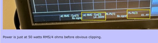
The positive waveform appears to be slightly lower in maximum value than the negative waveform, so I vote for distorted waveform due to clipping.
Do you suppose the waveform is distorted and not a pure sine wave?
I think both you & Ben Mah are right. I’ll repeat the measurements at some point, but I basically turned up the generator until I saw flattening of the sine waves and then turned it down just by a hair. Probably still clipping!
Thanks for the pickup!
Best,
Anand.
- Home
- Amplifiers
- Pass Labs
- F5m Redux