Thanks. Been busy with family and work but will try to adjust the amps tonight and post some pics if I'm still having trouble
I like it and it's working perfectly so far, but it's from AliExpress so I ultimately decided that I'm not comfortable including it with the kit (unknown certifications / quality control).As an aside I think Nelson B. you mentioned something about evaluating a lead combiner for the four SMPS units... Any conclusions?
Search for C13 to C14 4x splitter if you want one. They also make them with the regular NEMA 5-15p wall plug, but those seem to be less common.

One of my amps the fan runs fine and smooth and the lights stay on. Currently trying to set the bias on that one, but it is slow going. My multimeters are 2 cheapies so I don't know if that is making it tougher for me.
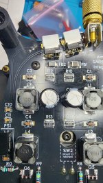
Here is some pics of the amplifier with the intermittent fan and flickering LED light. Let me know if you can see where the short is, or what to test for on the multimeter across the different components. Again, besides building the ACA Redux kit successfully, I have no kit-building or electrical engineering knowledge whatsoever.
Thanks for all the help.
You've got some touch up to do on those SMD components. I think you might need a higher temperature on your soldering iron to start and use a smaller tip if that's possible. However, my number one suggestion is to use liquid flux on all of those SMD joints. You have jagged/rugged looking solder joints there and you should have smooth even contours with a slight concave shape. Flux will help tremendously and so will more heat applied for a very short (2-3 second tops) duration. Smear flux all over the joint, touch for a couple seconds with a dry solder tip, and watch the solder flow smoothly into a nice concave and smooth shape. You don't need more solder, if anything you need a little less in my humble opinion.
Before you "reflow the solder" I'd use your multimeter in ohms/resistance mode to see if the outer edges of your feedthru caps are high resistance to ground (good), or near zero resistance to ground (bad). The middle of the feedthrough caps should have a very high megaohm resistance to the outer edges of the feedthru as well. Again, I point there as that's where my issue was.
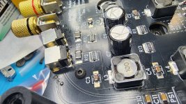
Here's some close up pics of my solder joints. I set my iron to 650°C and use a small tip (I use a bevel 1.5 to 2mm tip).

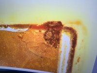
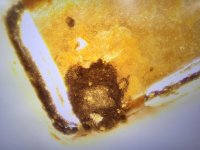
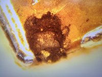
Here's some images under a stereo microscope of the failed thru-hole caps due to using too much solder and getting a short from the middle ground to edge under the cap (not visible from my QA check before power applied). I had smoke come put so it was obvious something was wrong.

Before you "reflow the solder" I'd use your multimeter in ohms/resistance mode to see if the outer edges of your feedthru caps are high resistance to ground (good), or near zero resistance to ground (bad). The middle of the feedthrough caps should have a very high megaohm resistance to the outer edges of the feedthru as well. Again, I point there as that's where my issue was.
Here's some close up pics of my solder joints. I set my iron to 650°C and use a small tip (I use a bevel 1.5 to 2mm tip).
Here's some images under a stereo microscope of the failed thru-hole caps due to using too much solder and getting a short from the middle ground to edge under the cap (not visible from my QA check before power applied). I had smoke come put so it was obvious something was wrong.
Attachments
-
 20240907_215330.jpg523.8 KB · Views: 77
 -
 20240907_215347.jpg536.5 KB · Views: 72
 -
 20240907_215353.jpg527.3 KB · Views: 74
 -
 20240908_112858.jpg436.1 KB · Views: 66
 -
 20240908_104326.jpg426 KB · Views: 63
 -
 20240912_175227.jpg406.9 KB · Views: 62
 -
 20240912_171207.jpg457.8 KB · Views: 56
 -
 20240912_171513.jpg569.4 KB · Views: 57
Last edited:
What solder are you using and what iron temperature? I agree it looks like lack of flux. I prefer to use flux core leaded solder and don't often need to apply flux separately.
Its a 60/40 lead-tin solder with a flux core. I hadn't used separate electrical flux paste. I didn't need it for the ACAs so I didn't buy any for this either. I was using the iron at 400 degrees C but maybe that needs to be higher?
How can I check the individual caps, resistors, etc with the multimeter to see where my problem lies?
I should be able to upload some higher res pictures of the amps later today. Thanks for all the help.
How can I check the individual caps, resistors, etc with the multimeter to see where my problem lies?
I should be able to upload some higher res pictures of the amps later today. Thanks for all the help.
Well, 400°C is too hot. I use 650°F (343°C) on my Hakko with great success. Flux paste for SMD should help get smooth, clean, shiny joints. I don't use flux on thru hole soldering.
Use you DMM to check around for shorts to ground. Place one probe on a chassis ground point, then use the other probe to measure resistance. For component joints that are supposed to be connected to ground (like the middle of those feedthru caps) you should get near zero ohms. For component solder joints that are not supposed to be connected to ground you should get open or very high resistance (say megaohms, or hundreds of kiloohms).
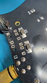
Note that Nelson has put together an amazing schematic with photos to help your brain convert symbols on a circuit diagram to the real world parts. Use that to see what should read grounded (zero ohms) vs what should not be grounded (very high resistance for the +/-24V rail voltage). I tried to get you started with the image below. Red circles are for rail voltage joints (high resistance or open) and black is for grounded joints. Note I didn't circle some joints for parts that have one joint on rail voltage, and one on ground. Those feedthru caps have 4 solder joint locations, middle two grounded, outside two on rails.


Use you DMM to check around for shorts to ground. Place one probe on a chassis ground point, then use the other probe to measure resistance. For component joints that are supposed to be connected to ground (like the middle of those feedthru caps) you should get near zero ohms. For component solder joints that are not supposed to be connected to ground you should get open or very high resistance (say megaohms, or hundreds of kiloohms).
Note that Nelson has put together an amazing schematic with photos to help your brain convert symbols on a circuit diagram to the real world parts. Use that to see what should read grounded (zero ohms) vs what should not be grounded (very high resistance for the +/-24V rail voltage). I tried to get you started with the image below. Red circles are for rail voltage joints (high resistance or open) and black is for grounded joints. Note I didn't circle some joints for parts that have one joint on rail voltage, and one on ground. Those feedthru caps have 4 solder joint locations, middle two grounded, outside two on rails.
That's hotter than it should be, the flux is likely vaporizing (into smoke) before the solder wets out. Use somewhere in the 300-350°C range for 60/40 solder.I was using the iron at 400 degrees C but maybe that needs to be higher?
How can I check the individual caps, resistors, etc with the multimeter to see where my problem lies?
- Unplug the amp
- Short each of the marked locations in the pic to ground (black arrow) using a meal tool or wire for a few seconds to discharge capacitors
- Measure ohms from each location to ground and report back
I prefer to use a flux pen when applying liquid flux. The stiff fibreglass tip not only dispenses just the right amount of flux, but it also buffs any oxide off the pad while you're applying it. One thing I've learned is to keep the pen sealed in a glass jar when not in use as it tends to dry out otherwise. Even if it does dry out, it can still be used by dipping the tip into a bottle of liquid rosin. The osmotic action of the fibreglass draws up enough flux for 3 or 4 applications before it needs to be redipped.
Prompted by @BeardyWan 's question about power supply cords, I took some time to tidy my setup.
3D printed brackets hold two or four supplies side by side with a bit of air space around them (they don't get all that warm but it can't hurt). Pips on the bottom of each supply hold the brackets in place. Braided 1/4" sleeving and some heatshrink completes the package. Files suitable for printing or editing are attached here and on the first post.


3D printed brackets hold two or four supplies side by side with a bit of air space around them (they don't get all that warm but it can't hurt). Pips on the bottom of each supply hold the brackets in place. Braided 1/4" sleeving and some heatshrink completes the package. Files suitable for printing or editing are attached here and on the first post.
Attachments
I just finished putting together my kit(s). I have been soldering audio kits together since the days of Heathkit, but this is my first try at SMD. Being of a certain age (the same as Nelson Pass), my hands have gotten very clumsy and shaky during the past year. So I want to say: if I can do SMD anybody can. I encourage folks to try!
The hard part for me was vision, needing some stronger close-up eyeglasses to see some of the tiny part labels.
One of the amps wouldn't bias up properly. After checking all the solder joints visually I ended up tracing the voltages through the power supply filter. Et voilá, the solder joint on the far side of L2, which looked fine, hadn't connected with the coil underneath where I couldn't see it. Re-soldered it and everything was fine.
I want to thank Nelson Brock for an amazing kit at a very fair price.
Nelson, clearly you like this DIY stuff and are very creative and thoughtful at it.
Yes, the vast majority of soldering failures on SMD boards are open-circuits. No electrical connection between component-lead and PCB-trace.
However, now that we know this fact, we can devise a tactic to hunt for opens. Use a continuity tester (DVM beeper) with sharp probe tips. Probe1 directly upon the component lead (NOT the PCB) and, following the circuit schematic, probe2 on the PCB at a pin which is supposed to be connected to this component lead. Beep=good, nobeep=opencircuit_at_this_component_lead .
However, now that we know this fact, we can devise a tactic to hunt for opens. Use a continuity tester (DVM beeper) with sharp probe tips. Probe1 directly upon the component lead (NOT the PCB) and, following the circuit schematic, probe2 on the PCB at a pin which is supposed to be connected to this component lead. Beep=good, nobeep=opencircuit_at_this_component_lead .
Good magnification and a well lit (you want a minimum of 1000 lm / m2 per IPC-A-610) work surface are very important to have a chance to be successful with SMD assembly and rework. For magnification I have always used (for many many years): "Donegan DA-3 OptiVISOR Headband Magnifier, 1.75X Magnification Glass Lens Plate, 14" Focal Length" both at home and at work (I work in the electronics industry).The hard part for me was vision, needing some stronger close-up eyeglasses to see some of the tiny part labels.
It's probably been posted before, but I'll post it again.... I use these magnifiers with great success for SMD soldering and other purposes (QA checks). They come with a bunch of different interchangeable lenses for various magnifications and a good LED for illumination. They also easily flip up out of the way when you don't need them. I can even wear with my glasses, albeit a little odd with two sets of lenses on.
Nelson, not sure if you have answered earlier in this thread but is there a possibility to sell only the pcb boards as I have all the stuff to populate from my stash?
I understand the kit is more attractive for someone who doesn’t want to go around looking for parts and it’s a fantastic priced kit.
Thanks
I understand the kit is more attractive for someone who doesn’t want to go around looking for parts and it’s a fantastic priced kit.
Thanks
That's hotter than it should be, the flux is likely vaporizing (into smoke) before the solder wets out. Use somewhere in the 300-350°C range for 60/40 solder.
View attachment 1399657
- Unplug the amp
- Short each of the marked locations in the pic to ground (black arrow) using a meal tool or wire for a few seconds to discharge capacitors
- Measure ohms from each location to ground and report back
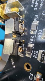
Hey, finally had time to work on these.
Green to ground is 406 ohms.
Orange to ground is 405 ohms.
Blue is super-high ohms (outside multimeter range)
Red is 0.5 ohms.
Just completed. Purchased these at Burning Amp 2024, but didn’t open the box until Christmas. Impressive kit, clear instructions, very fun build. Really impressive sound. Fans are inaudible, as advertised. Looking forward to seeing how much power this heatsink/fan combo can manage in future kits!
- Home
- Amplifiers
- Pass Labs
- F5m Redux