
Hi,
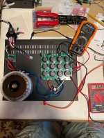
I've now finished my F5m amplifier. I built it into the large Modushop 4U400mm enclosure. (PassDIY enclosure)
With 0.66V across the 0.47 Ohms (=1,4A) , the heatsinks barely get warm.
What's your experience with the larger enclosures?
What would be your recommendation?
How high can I go with the current?
Best Regards
Barossi
^ That sounds about right. Nelson put estimates for temp rise in the article.
You can always try a little higher, particularly if you have lower impedance speakers and/or if you just want to see if you hear a difference.
The "rule of thumb" is to not to exceed 35W dissipation per device, but I'm sure people have pushed them further.
You can always try a little higher, particularly if you have lower impedance speakers and/or if you just want to see if you hear a difference.
The "rule of thumb" is to not to exceed 35W dissipation per device, but I'm sure people have pushed them further.
Great idea. I'll do itSend some photos, and I'll happily include them.
By the way have you noticed that the output wires on the Antek 3218 are 12AWG but the holes for them on the power supply PCB are 12AWG max. It's a shame to have to rig an adatation to the smaller wire diameter. Maybe a possible correction if further runs of pcb are made.
Mine is in a 3U 400 mm and it doesn't get hot, toasty but not really hot. You should have plenty of sink!Hi,
I've now finished my F5m amplifier. I built it into the large Modushop 4U400mm enclosure. (PassDIY enclosure)
With 0.66V across the 0.47 Ohms (=1,4A) , the heatsinks barely get warm.
What's your experience with the larger enclosures?
What would be your recommendation?
How high can I go with the current?
Best Regards
Barossi
Russellc
I recently build the F5, does the F5M sound different and is the Aleph J still the best sounding class A amp to built?
Great idea. I'll do it
By the way have you noticed that the output wires on the Antek 3218 are 12AWG but the holes for them on the power supply PCB are 12AWG max. It's a shame to have to rig an adatation to the smaller wire diameter. Maybe a possible correction if further runs of pcb are made.
The new boards for CPU fan cooler arrived and were set to 1.4 Amps. It has two inputs, one with a filter 1.2k 47k 470pf a perfect square wave test and one as the original 10k 47k selectable with jumper.We are waiting to hear the amplifier.
Attachments
Last edited:
I am attempting a dual mono fully balanced F5m using two boards per channel in a 5U chassis and the assembly has got to installing the jumper wire from R5 on the -ve board to the R4 Q1/Q2 junction on the + board and am at a loss understanding the drawing I have.do I lift the -ve board R5 - ground connection or just leave it and bypass R5 on the +ve board?
Attachments
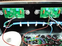
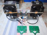
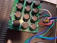
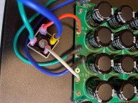
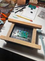
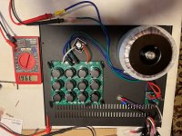
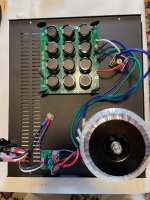
@ItsAllInMyHead Following on your suggestion, here are some photos of the power supply configured with one rectifier. This particular configuration is for my version of the F5m with an external power supply feeding two separate amplifier modules with individual heat sinks. I decided I wanted an external power supply for use with future amp builds. This also opens the door to the possibility of making the F5m a monoblock amp with external power supplies if I build a second power supply at some point in the future. The whole thing is not done yet but I include a shot one of the amp modules just for fun. I am using Neutrik powercon connectors to take the DC power from the power supply to each amp channel module.
Attachments
@sndlvr: you might want search for the discussion on threads (I can't remember which thread and postings or I would provide links) about the use of PowerCon for DC. As I recall, Neutrik does not recommend use of PowerCon for DC because it is not rated for DC. There recommendation may be to limit their liability as they did not pay for the PowerCon to be tested for DC rating; but my recollection is that a DIYAudio member called Neutrik and received a detailed technical answer as to why the PowerCon was not a good idea for DC.
However, other DIYAudio members had disagreement about whether the Neutrik position was relevant at the current level being used for Pass amps.
At least look at the threads and consider the issue.
However, other DIYAudio members had disagreement about whether the Neutrik position was relevant at the current level being used for Pass amps.
At least look at the threads and consider the issue.
Part of the reason to avoid Powercon for DC — or the very solidly built Neutrik XLR jacks — is insurance that the wrong source is never plugged in. When it’s your own equipment this error may be unlikely, but keeping a dedicated plug standard will avoid the chance your kid, friend or house cleaner plugs your DC jack into the wall.
I guess that is reasonable where neutiks are in common use for AC but in my house there are no Neutrik AC connections. In fact, I have never seen them used anywhere, I'm in the US. For the sake of argument what would be a better choice to run the 24 vdc power to the remote amp modules?
Also I noticed while searching the https://www.diyaudio.com/community/...rd-power-chassis-for-pass.380146/post-7398952 thread that @Nelson Pass seems to suggest putting some additional capacitors in the remote amp module would be a good idea. Presumably to help clean up any spurious AC picked up by the connecting wire. Can anybody comment on the necessity of doing this and how much capacitance it should be? I was planning on leaving all the capacitors in the remote power supply box.
Also I noticed while searching the https://www.diyaudio.com/community/...rd-power-chassis-for-pass.380146/post-7398952 thread that @Nelson Pass seems to suggest putting some additional capacitors in the remote amp module would be a good idea. Presumably to help clean up any spurious AC picked up by the connecting wire. Can anybody comment on the necessity of doing this and how much capacitance it should be? I was planning on leaving all the capacitors in the remote power supply box.
If one uses 4 or 5 contact XLRs, the issue of plugging in the wrong source is likely eliminated. The vast majority of people do not use anything other than 3 contacts.
Using XLRs to provide power to preamps and other low level power equipment seems OK. XLRs are designed to accomodate providing phantom power to equipment such as condenser and tube microphones, and ribbon microphone pre/preamps. I would NOT, however, consider using XLRs to convey DC power at amplifier PS currents. That is my own bias; YMMV.
Using XLRs to provide power to preamps and other low level power equipment seems OK. XLRs are designed to accomodate providing phantom power to equipment such as condenser and tube microphones, and ribbon microphone pre/preamps. I would NOT, however, consider using XLRs to convey DC power at amplifier PS currents. That is my own bias; YMMV.
@Halauhula Well the input to the power supply is fused at 2 to 2.5 amps AC so am I wrong in thinking that the DC output to the amp channels could be any more than that, total?
Note: Powercons are rated for 20A 127V AC. Seems like a pretty good safety margin but maybe I am missing something. I appreciate all guidance.
Note: Powercons are rated for 20A 127V AC. Seems like a pretty good safety margin but maybe I am missing something. I appreciate all guidance.
Last edited:
@sndlvr: there is a difference between total power transmitted between AC and DC. You may research that topic.
@Tube Radio: by coincidence I recently helped a theatre and AV provider set up a lighting and sound system which used, among other things, 16 DMX LED lighting fixtures. I was informed in passing that fixture cost either $600 or $1200 dollars. It was the first time I’ve had to set up DMX, so it was a learning experience. Each fixture was powered by AC interconnects terminated either by IEC or PowerCon connectors; the signal was transmitted by special cables with controlled impedance and 3 pin XLRs. Based upon my experience, I feel safe to say that 5 pin XLRs are very uncommon in most audiophile homes.
@Tube Radio: by coincidence I recently helped a theatre and AV provider set up a lighting and sound system which used, among other things, 16 DMX LED lighting fixtures. I was informed in passing that fixture cost either $600 or $1200 dollars. It was the first time I’ve had to set up DMX, so it was a learning experience. Each fixture was powered by AC interconnects terminated either by IEC or PowerCon connectors; the signal was transmitted by special cables with controlled impedance and 3 pin XLRs. Based upon my experience, I feel safe to say that 5 pin XLRs are very uncommon in most audiophile homes.
Last edited:
Well the input to the power supply is fused at 2 to 2.5 amps AC so am I wrong in thinking that the DC output to the amp channels could be any more than that, total?
It is a power supply's input and output power that is roughly the same (discounting losses), not the input and output current.
The magnitude of the supply's output DC current could be much larger than the magnitude of the input AC current.
- Home
- Amplifiers
- Pass Labs
- F5m kit