I don't solder the male Faston to the female Faston after making the final connection if that's what you're asking. It's still "quick connect", as intended. Quality connectors (TE, Molex, etc.) will fit tight. The thin cheap no name crap? Maybe / probably not...
Definitely verify the size of the tabs and use the correctly sized mate, common sense there. The SCHURTER PEM I used on my last project had 6.3mm connectors (.250").
Definitely verify the size of the tabs and use the correctly sized mate, common sense there. The SCHURTER PEM I used on my last project had 6.3mm connectors (.250").

Last edited:
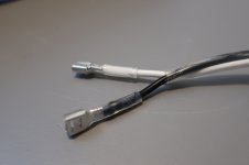
Ah, ok, thanks @birdbox that makes sense now. I thought the suggestion was to solder all the wires and not use any spade connectors at all. I see the fastons for the 4 top leads which are the ones I butchered trying to solder. The other 3 pins could easily be soldered as I did the earth ground.
For the Fastron I'm finding out that the width, tab thickness and tab length need to be considered when matching them up with a connector. Most likely why mine would not fit without force. I'm guessing there are only a few standard sizes used but digikey has a wide range of choices in their search. This has been the biggest 'gotcha' for me so far by far as my first build. Also could be dangerous considering badly matched connectors could easily come loose. ( I would have 'pinched' them with pliers thinking all was good but learned today that is not the case )
For the Fastron I'm finding out that the width, tab thickness and tab length need to be considered when matching them up with a connector. Most likely why mine would not fit without force. I'm guessing there are only a few standard sizes used but digikey has a wide range of choices in their search. This has been the biggest 'gotcha' for me so far by far as my first build. Also could be dangerous considering badly matched connectors could easily come loose. ( I would have 'pinched' them with pliers thinking all was good but learned today that is not the case )
I used the faston connector with insulation removed, crimped and soldered ( belt and suspenders folks ) and the transparent 1/4" 3:1 shrink tubing recommended by @birbox and the result is VERY GOOD. It clips onto the lead with just the right amount of force and can be removed without the faston crimp failing. The transparent shrink tubing ads additional peace of mind by allowing the builder ( me ) to see a good crimp and solder and will prevent a short if it comes loose.
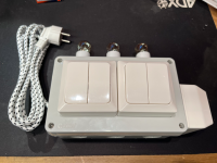
Also, for anyone else having trouble attaching the terminals to the PEM, the switch CAN BE POPPED OUT! Thanks again @birdbox for pointing this out to me.
Also, for anyone else having trouble attaching the terminals to the PEM, the switch CAN BE POPPED OUT! Thanks again @birdbox for pointing this out to me.
Attachments
Last edited:
I'm still a ways away from powering up my F5m, but starting to plan on building a 'dim bulb tester'. Should I build any old design or does anyone have a recommendation for a good one?
I'm also ordering a 'variac'. I've never used one before. Is a 5 amp 500W ok or does someone have a decent one to recommend?
For the transformer, has anyone else tried using the CL-200 from antek? If so, did you drill holes the bracket or the base plate since the holes do not match up?
CL-200 Bracket
Regular old dim bulb tester is fine. Honestly for this project, a Variac is probably not needed but why not have it. Before initial powerup, Ohm check the metal case of the mosfets to chassis gnd. Then check V+ to gnd and V- to gnd to make sure there are no shorts.
The biggest thing to check after you start the amp and the bulb doesn't go crazy is if you can adjust the bias and DC offset a bit. Make sure they cooperate well. If not, unplug it and start checking components. If the DC offset and the bias behave, then there are generally no substantial problems and you can remove the dim bulb tester and start adjusting things.
I haven't tried the vertical mounting bracket but they sure look great.
Ok good info. I'll make sure the mosfet are not shorted to gnd. Since it's my first build, what do I ensure 'cooperate well'? Do I turn each trim slightly to see if the bulb brightens up or is inconsistent?
First check to make sure the DC offset is not some absurd number like 10 plus volts. Next check across each Source resistor and adjust the bias pot for each mosfet a little bit to make sure that the bias can be adjusted both directions. If those check out, then you are probably good to go. Most people start with the bias set to minimum which is probably smart. Once you confirm these things, then you can remove the bulb tester and adjust the bias etc.
On mine in particular, I didn't even use a bulb tester 😬 but then again, I have built enough amps to know that it was probably going to work right out of the gate... And it did.
On mine in particular, I didn't even use a bulb tester 😬 but then again, I have built enough amps to know that it was probably going to work right out of the gate... And it did.
I use a variac to bring up new power amps. Initial voltage is set to 90 Vac, make sure magic smoke stays in place, then slowly increase to 120 Vac and check bias current.
Once the initial setting is in place, I plug the amp into house AC and begin the hour long warmup prior to setting final DC Offset and bias. Let the amp cool down completely, then redo another hour warmup and re-check bias. This has proven to be an effective method for catching construction issues and early device failures.
Once the initial setting is in place, I plug the amp into house AC and begin the hour long warmup prior to setting final DC Offset and bias. Let the amp cool down completely, then redo another hour warmup and re-check bias. This has proven to be an effective method for catching construction issues and early device failures.
@TungstenAudio great info, thanks. Do you also use a dim bulb tester? Would it prevent magic smoke for testing at 90Vac?
I don’t have a dim bulb tester. Tungsten filament bulbs in the necessary wattages have been unobtainable in local stores for a few years.
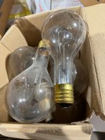
I have a dim bulb tester and I can purchase the Tungsten filament bulbs I need, from Amazon.com . The "trick" is to realize that it remains legal to sell incandescent bulbs for a few niche applications, such as appliances (refrigerators), and hard-to-access outdoor installations, so-called "Rough Duty" bulbs. Take a look. Amazon is happy to ship both of these to ultra-woke, ultra-environmentally-conscious San Francisco.
They are available. They are not cheap.
_
They are available. They are not cheap.
_
Attachments


I don't own a variac. I've powered up at least a dozen power amps with linear power supplies & not ever had an issue that I couldn't identify with a dim bulb in series on the mains.
I still see some available on the home depot and canadian tire sites so I expect you should be able to find them locally. They're mostly 'specialty bulbs' and are not cheap, but at least you can get them.
For example, here's one:
https://www.homedepot.ca/product/ph...light-bulb-soft-white-2700k-2-pack/1000137991
For example, here's one:
https://www.homedepot.ca/product/ph...light-bulb-soft-white-2700k-2-pack/1000137991
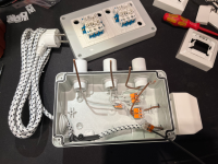
Low wattage incandescent bulb are still legal here in Norway. Used for example in kitchen stoves as I guess led’s won’t like the heat. So I made an overly complex DBT using three 25W bulbs paralleled via independent switches so I can vary the load. A fourth switch bypasses the bulbs and sends full power through to the DUT.
Attachments
- Home
- Amplifiers
- Pass Labs
- F5m kit