I do have a WiFi repeater close by but the buzz is still there when it is switched off.
A DAC is connected to the Whammy input but the buzz remains when it is fully disconnected.
A DAC is connected to the Whammy input but the buzz remains when it is fully disconnected.

Logic800 - You might try bonding the input signal grounds together at the input sockets. Same can be done with the output sockets of the Whammy.
I don't know if you were following the thread earlier this month when I reported a similar low-level buzz problem. I experienced mixed results on removing/swapping cables, but then discovered that the buzz was absent on a cold amp, but present as it warmed, regardless of connections. Some detail on this is provided hereHelp with buzz.
Your problem may be different, and related to a ground issue via the RCA shields, but before you go too far, check the above and consider how much time you permitted between power-off and power-on (I assume you powered down before RCA cable swaps).
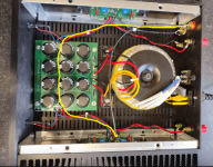
I will note that my issue was solved after I added extra capacitance and rerouted my wiring (which had faults yours doesn't). Although I'm not positive which was the bigger help, it is possible the ultimate source of my problem was the rather close spacing between the transformer and the F5m channel PCBs. Your unit has a narrow chassis and also seems to have a similarly close spacing.
The Whammy works OK into a Quad 303 and as a headphone amp.
I will try the bonding recommendation.
I also worried about the close proximity of the transformer and the amp boards, but if this was a problem I would think the amp would buzz without input leads. I might be wrong.
Thanks for all the suggestions.
I will try the bonding recommendation.
I also worried about the close proximity of the transformer and the amp boards, but if this was a problem I would think the amp would buzz without input leads. I might be wrong.
Thanks for all the suggestions.
Update to the above. The Whammy's output sockets are already bonded, and I think there is an improvement when I do a 'rough-and-ready' bonding of the amp's input sockets. Will do it properly tomorrow.
Hi
I have two questions:
1. I have quite a few of the old IRF240 and IRF2940 transistors. How audible is the difference to the new transistors that are specified for the F5M?
2. Bias and DC-offset seem to be very sensible to even small air movements. I assume this is due to the input transistors. Wouldn't it be of help to put small plastic covers over them? (I have a Audio Research PH-1 were they do this to the input transistors)
But if it was internal pick-up, wouldn't it buzz without the input cables connected? Which it doesn't.
There is more loop area for induction coupling once the input cables are connected and un-wanted noise currents are flowing through the interconnect signal return. We only want signal current on there without the nasties. It was just something to try that may / should be better with this sort of layout, that's all.
OK, understood, thanks. Currently in pub en route to curry in Brick Lane, so best I look at tomorrow!
Help with buzz. Now that I have the heat issues under better control, the next thing on the list is a faint 100Hz buzz when my ear is up against the speakers. It doesn't change with volume and isn't there with input cables removed. In fact it isn't there when the input cables are attached but not connected to the preamp (a Whammy). When I connect the preamp the buzz occurs even if it is switched on or off, or even unplugged from the mains socket. Unplugging anyone of the cables (from preamp to amp) stops the noise so I tried removing the return shield on one cable but the buzz returned.
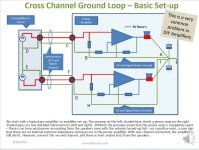
diyAudio member Bonsai (Andrew Russell) has much information on fighting amplifier noise. This is one of his articles:https://hifisonix.com/wp-content/uploads/2019/02/Ground-Loops.pdf
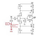
You may have a cross channel ground loop problem. See excerpts from Andrew Russell's article. william2001's suggestion is one of Andrew Russell's suggested cures. This alone may not cure the problem. The other cure is to add a Hum Breaking Resistor to each amplifier channel.
Some excerpts from Andrew Russell's article attached below.
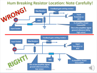
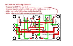
If you wish to try adding the Hum Breaking resistor, also see below.
Attachments
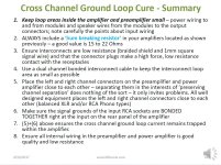
Thanks for the very comprehensive response. I will try the 'low hanging' wiring mods tomorrow and report back.
A quick question; isn't the 10ohm thermistor on the PSU board, that connects 0V and chassis ground, doing the same job as a HBR?
Hi 6L6
Many thanks for your answers!
I remember some year ago in HiFi shop I heard one of those powerful PASS Amps. It had the same sound signature like my small F5.
Many thanks for your answers!
I remember some year ago in HiFi shop I heard one of those powerful PASS Amps. It had the same sound signature like my small F5.
With the wiring and bonding changes the buzz is much improved, such that if it were at this level initially I wouldn't have bothered to do anything about it. I will however try the HBR mod at a later date. Again, thanks to all who gave advice.

Just measured heatsinks via transistor mounting threaded hole and getting 46 degrees C each with 20 degrees room ambient. This is one fine sounding amp, and all for less than £300. Over and out.
A quick question; isn't the 10ohm thermistor on the PSU board, that connects 0V and chassis ground, doing the same job as a HBR?
Not the same, that one is for safety, and allows fault current into the chassis and the IEC safety ground.
A 10R resistor between the input socket common and the audio circuit common reduces ground loop hum/noise.
Florida, yesterday, afternoon no AC, 56C top center of heatsinks, approximately 86 degrees F (30C) room temp, .52 and .49 volts per channel after 3 hours of playing. Not an amp you want to hold hands with. Call me crazy, but sound reminds me of an FET-10 I used to own.
- Home
- Amplifiers
- Pass Labs
- F5m kit