gut feeling...neither
What about these then?
Attachments

nope Bubba, no sound in any way you did show
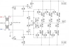
keep pair of original 220uF caps on input, upper end of secondary to their mid point, lower end of secondary to GND
you can't go in DC coupled, period.
keep pair of original 220uF caps on input, upper end of secondary to their mid point, lower end of secondary to GND
you can't go in DC coupled, period.

just keep them coming, it's very well known who's dumbest around, so all your efforts are fruitless

........
so no way to eliminate AC coupling caps ... ? 🙁
What about C3 and C4 value ... Would 10uF polypropylene cap work here instead of 220uf electrolytic?
nope
you need them in that size to bootstrap gate to gate
besides, I'm pretty sure that you have much weaker links in your signal chain , up to this point
you need them in that size to bootstrap gate to gate
besides, I'm pretty sure that you have much weaker links in your signal chain , up to this point

nope
you need them in that size to bootstrap gate to gate
besides, I'm pretty sure that you have much weaker links in your signal chain , up to this point
ok, Thanks!
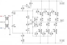
I attached final for whoever else would like to do it.
just build F4 as is
Maybe you are right adason.
Do you know if attached schematic is the last version?
Attachments

Member
Joined 2009
Paid Member
what about some Frankenstein option using F6 topology to connect coil to output instead of F4 ?
Does R9 need to be 5k?
I needed to change R9 to 5K to get it to bias correctly.
Perhaps it depends on the jfet Idss.
I needed to change R9 to 5K to get it to bias correctly.
Perhaps it depends on the jfet Idss.
JFets are left of that, having nothing with mosfet biasing
you can leave them, JFets, at neighbor's, if you want
🙂
you can leave them, JFets, at neighbor's, if you want
🙂
As far as C1-C4:
Do they all must be the same? or e.g.: C1,C2 220uf Non-Polar and C3,C4 1000uF Polar?
Could C1 and C2 be rated for 25V since they only carry signal ...
Do they all must be the same? or e.g.: C1,C2 220uf Non-Polar and C3,C4 1000uF Polar?
Could C1 and C2 be rated for 25V since they only carry signal ...
C1 C2 are coupling capacitors, keep them - the F4 can not be made DC coupled.
C3 C4 are “rail boosters” to make sure that the Jfets have sufficient voltage on peaks.
There’s no real reason to make the values different than as designed.
C3 C4 are “rail boosters” to make sure that the Jfets have sufficient voltage on peaks.
There’s no real reason to make the values different than as designed.
C1 C2 are coupling capacitors, keep them - the F4 can not be made DC coupled.
C3 C4 are “rail boosters” to make sure that the Jfets have sufficient voltage on peaks.
There’s no real reason to make the values different than as designed.
Got it thank you.
So C1 and C2 220uF rated for 25V are ok? ... I got such of high quality thinking of using them ...
Yes, will be fine.
Remember that physically large capacitors have a tendency to pick up buzz and humm and more than something or normal size...
Remember that physically large capacitors have a tendency to pick up buzz and humm and more than something or normal size...
- Home
- Amplifiers
- Pass Labs
- F4 power amplifier