Which of the TL431's listed on Farnell is the one to go for? Also can I use 221R for gate stopper resistors instead of 150R tia
Your Search Results | Farnell UK | Results
That didn't work properly.I thought that I had narrowed it down to a few not the 175 shown on the link.
Your Search Results | Farnell UK | Results
That didn't work properly.I thought that I had narrowed it down to a few not the 175 shown on the link.
Last edited:
that's why I strongly despise public BOMs - every second guy is using wrong BOM
I am with you on that, but I thought the one from the DIYAudio store would be correct. I have certainly learned my lesson.
looking at sch (mentioned in my previous post) all differences are irrelevant ......... except R8 (upper TL431 resistor) - make it 27K , as Papa intended
I replaced R8 and am now able to bias each channel up to 350 mV. There was no problem with my build other than the wrong values from the DIYAudio store BOM.
Thank you Zen Mod for helping cleanup someone else's mess.
don't judge them too harsh
it's easy to make mistake , while trying to satisfy zillion different demands
however - decrease input JFET source resistors , as per Pa's schematic
next time - study schematic , try to understand each part's role , and make your own BOM , needed for shopping list
it's easy to make mistake , while trying to satisfy zillion different demands
however - decrease input JFET source resistors , as per Pa's schematic
next time - study schematic , try to understand each part's role , and make your own BOM , needed for shopping list
I have 4 channels of F4 stuffed and biased. 4 channels of Ba3 stuffed and biased. Goal is a balanced (intergated) Bba3/F4. Currently I have a nice regulated supply for the Ba3 boards and two FW style power supplies for F4 (BF4). I have one 400VA 18volt toroid and one 300VA 18volt (in my F5). I am planning on getting a 600va for 4 F4 boards, put 400VA into F5, use 300VA currently in F5 to run 4 Ba3 channels. I guess the question is, is a 600VA 18v sufficient to power 4 F4 boards? One 300VA 18v adequate for 4 channels of Ba3? Sounds ok to me. I think the F5 will enjoy 400VA rather than 300VA currently in residence. Thanks! PS Ba3 boards biased to 1 volt, F4 boards biased to 200mv. I could leave the 300 in F5 and use 400 for Bba3.
May I ask what regulated supply you are using for the BA3b?
Thanks
It's an AMB Sigma 22 bipolar supply. Kind of pricey to build (~$100), but it looked like fun. With a 26V transformer (60hz mains) I can get 24 regulated volts. Here's a link. The σ22 Regulated Power Supply
I also like the TubeCad bipolar supply, but it is slightly too limited in voltage, at about 20. New bipolar low-voltage power supply for solid-state projects.
I'm going to use 2) 400VA 18v toroids for F4 and a 200VA 26v toroid for the bba3, unless someone more knowledgable than I thinks I should up the 26v to 300VA. Fun. It's all an excuse to solder stuff.
FWIW, the voltage limitation of the Tubecad is arbitrary - John says the limits are about 20V as he is using 25V caps. That's very good practice (which I agree with) to de-rate like that, but you could run them at the full 25V, and could easily have more voltage quite safely with different caps.
BA3b + crippled F4 up and running on workbench
Hopefully in system this weekend
Modular so I can lift it
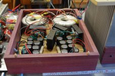
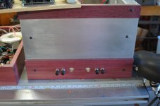
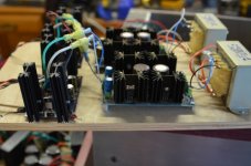
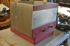
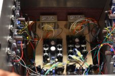
Pix - power supplies, main box which houses F4 boards and BA3b set-up, BA3b boards courtesy of buzzforb(many thanks), integrated components
Will try to get pix of inside a bit later
Hopefully in system this weekend
Modular so I can lift it
Pix - power supplies, main box which houses F4 boards and BA3b set-up, BA3b boards courtesy of buzzforb(many thanks), integrated components
Will try to get pix of inside a bit later
Attachments
FWIW, the voltage limitation of the Tubecad is arbitrary - John says the limits are about 20V as he is using 25V caps. That's very good practice (which I agree with) to de-rate like that, but you could run them at the full 25V, and could easily have more voltage quite safely with different caps.
That's good to know. I built a couple with 35V caps, and I might ramp up the voltage, now that I know I can. What's another transformer among friends?
Time for an update.
Last time I posted my F4 did not sound right. I found out it had GR JFETs and lowering R3 and R4 from 10R by adding a 1R parallel dit not really help.
I asked my friend to replace the GR's with BL's but he was unable to work on the amp and will be out of the country till december. I did not want to wait that long so decided to try it myself.
Last year I had to remove a JFET in my first poweramp build, an Aleph J, and spent a lot of time on it (cursing all the time), so I know that desoldering is an art that I have not (yet) mastered. There must be a better way!
I tried a heatgun (500 - 550 degrees C) with a 9 mm reduction nozzle directed at the back of the PCB and was able to pull the JFETs out from the front. Worked great!
Next problem was that the holes were blocked with solder. Pump or braid did not do the trick, so I drilled them out manually (turning the tiny 8 mm drillbit by hand). Getting the new JFETs in was a piece of cake.
After biasing the amp at 200 mV and 0 V DC offset I was worried that the sinks were getting hot. I rebiased at 175 mV, let it cook for an hour and checked again. Next step will be to mount the front panel, close the lid, re-bias, cook for an hour and a final re-bias. I expect to do that tonight and then hope to hear some magic!
Thanks to everyone for your help.
you declared as problem few things ,which ppl are doing every day , again and again , as trivial routine
what could you say for any multi-leg chip replacing procedure ?
there are plenty of on-line tutorials , for almost everything
what could you say for any multi-leg chip replacing procedure ?
there are plenty of on-line tutorials , for almost everything
you declared as problem few things ,which ppl are doing every day , again and again , as trivial routine
what could you say for any multi-leg chip replacing procedure ?
I know that desoldering is an art that I have not (yet) mastered 🙂
add solder to all 3 pins
heat them all in same time , pulling transistor out ;
then use solder sucker or solder wick
desolderingtutorial - YouTube
heat them all in same time , pulling transistor out ;
then use solder sucker or solder wick
desolderingtutorial - YouTube
...also, I've found helpfull: set a piece of that solder wick between the pins/feet and saturate it with solder, then do as Zen Mod suggests. Aceton cleans most of the junk quite nicely from the PCB. 😎
After changing the JFETs (from GR to BL), rebiasing, etc. I have finally been able to listen to my F4. It still does not sound as good as I had hoped. Perhaps the problem is that the F4 is revealing problems in the rest of the chain (source, preamp) as some have suggested.
It sounds to me as if there is very little energy in the mid frequencies (compared to both bass and treble). I think I need a signal generator and a scope to check that. I will check youtube and other internet sources for instructions.
I am going to re-read this thread and check every part in the F4 to see if I can find out what is going on.
Will keep you posted.
Albert
PS Just completed my F5 and it sounds great!
I had similar impressions with my F4s, a bit hidden midrange. Then I changed R3/R4 from 22.1 to 10Ohm and it is definitely better now. My source at the moment is just an old PC, so that may be part of the problem. I started building Impasse...
I don't quite get the point of 1N4148 at the gate of the Jfets.
Has this been previously explained somewhere?
Has this been previously explained somewhere?
- Home
- Amplifiers
- Pass Labs
- F4 power amplifier