Thanks for the tips.
Am listening to one of the F4's in my study at the moment. There is no hum, no noise, nothing wrong there. But the sound is not right, it sounds more like a cheap transistor radio than I know it should.
Listening to it again, I think that not all frequencies are amplified at the same level. There is very little midrange.
Am still baffled what the cause is. I am so used to binary logic (things either works or don't) that it is difficult to understand what the problem could be. I guess I should have studied electrical engineering instead of mathematics!
IEC Filter
The same IEC filter is used on a DIY Aleph J and that amp sounds great. I will leave it in for now.
Bias
For as far as I know my friend checked the bias on all mosfets (final setting was 250mV), but I will ask him to do so again with the second F4 that is at his place.
Mounting screws
I will also ask him about the screws and nylon washers. Good tip!
Will report back!
Thanks,
Albert
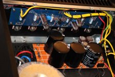
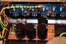
I opened up the F4 in my study and have taken some photo's. As you can see that I have removed the 2 top/middle screws from the PCB's as suggested by Itsmee. The PCB's were not damaged beneath the washers, so I do not think this was an issue.
You can also see the 1R2 resistors I added previously (parallel to R3 and R4, as suggested by Nelson; it does not look nice but it was just to see if it solved the problem).
Let me know if you require photo's of any particular details.
Thanks,
Albert
You can also see the 1R2 resistors I added previously (parallel to R3 and R4, as suggested by Nelson; it does not look nice but it was just to see if it solved the problem).
Let me know if you require photo's of any particular details.
Thanks,
Albert
Attachments
It depends on the ambient temperature.At .230 volts the heat sinks on my F4 ( in the DiyAudio 4u case ) were pretty hot. Seems odd that your sinks at .250 wouldn't be that hot. Just throwing it out there.
I adjusted my bias in the summer....heatsinks got hot to touch....in winter they are hardly warm.
Let me know if you require photo's of any particular details.
Thanks,
Albert
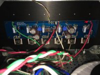
I don't understand your input cables - could you please provide better pictures or a diagram. It seems to me like you could have some ground loops with your XLR plugs... but hard to tell.
Do you run it balanced or single ended?
It depends on the ambient temperature.
I adjusted my bias in the summer....heatsinks got hot to touch....in winter they are hardly warm.
The sinks get hot, but not too hot. I haven't measured the exact temp but my DIY Aleph J runs hotter (in a 400mm 4U case). The Aleph J operates on a slightly higher voltage (2 x 21V rather than 2 x 18V transformer).
I don't understand your input cables - could you please provide better pictures or a diagram. It seems to me like you could have some ground loops with your XLR plugs... but hard to tell.
Do you run it balanced or single ended?
So far I have been running it single ended only.
The photo's in message #4122 are of the F4 that I have in my study (the photo's in message #4114 were sent to me by my friend some time ago and I think they are the other F4 amp).
I think I have all connections as they should be. They are as follows:
- Cinch, XLR and speaker connectors are isolated from chassis.
- Left cinch signal and ground connected to IN and GND respectively on the Left channel PCB.
- Right cinch signal and ground connected to IN and GND respectively on the Right channel PCB.
- XLR signal pins connected to Left and Right cinch signal.
- XLR ground connected to Right cinch ground only.
- Left Speaker + and - connected to OUT and GND respectively on Left channel PCB.
- Right Speaker + and - connected to OUT and GND respectively on Right channel PCB.
- GND on Left channel PCB to logical ground starpoint.
- GND on Right channel PCB to logical ground starpoint.
- + from Positive PSU to V+ on Left and Right channel PCB's.
- - from Negative PSU to V- on Left and Right channel PCB's.
- 0 from Positive PSU to logical ground starpoint.
- 0 from Negative PSU to logical ground starpoint.
- logical ground starpoint connected to one leg of CL-60. Other CL-60 leg connected to chassis.
- Chassis connected to earth terminal on power input.
check Iq of Jfets
check Iq of all mosfets
My friend has sent me measurements:
Bias is now 200mV (it is summer and the sinks were getting rather hot).
Voltagedrop across R3 and R4 (this F4 has 10 Ohm resistors):
Left channel R3 37.7 mV.
Left channel R4 37.7 mV.
Right channel R3 37.7 mV.
Right channel R4 37.7 mV.
He noted that these voltages rise very, very slowly. He does not expect that they will rise above 38 mV.
N.B. In order to avoid trouble while placing the probes he switched the amp off between measurements.
Are these measurements as expected?
Voltagedrop across R3 and R4 (this F4 has 10 Ohm resistors):
Left channel R3 37.7 mV.
Left channel R4 37.7 mV.
Right channel R3 37.7 mV.
Right channel R4 37.7 mV.
Correct me if I am wrong, but I would expect these voltages to be a bit closer to 50 mV.
remove 10R resistors
those JFets are sissy
Can it work properly with these jfets?
I tried the other F4 with 1R2 parallel to 10R. Same bad sound.
Should I get BL jfets?
I can get BL grade JFet's that are supposed to be 7.3 mA. I want to make sure this will solve the problem. Zen-mod?
first try existing ones without source resistors
if that's better , chase proper BL ones
Thanks Zen Mod.
I will try to remove the 1R2 parallel to 10R and replace by wire in the F4 in my study. Will try this as soon as I can get someone to help me lift the amp.
Will report back.
Albert
I have a question - in this schematic, what are D3/D4 good for? They are not part of the schematic in the F4 service manual.

Many Thanks
Sven
Many Thanks
Sven
Last edited:
- Home
- Amplifiers
- Pass Labs
- F4 power amplifier