The circuit I posted above would not have worked for other reasons, r27 is to small. It would have to be about twice as large. Also the bias supply voltages have to be raised for it to work properly. But it would not be practical since r27 is to large as Zen pointed out.
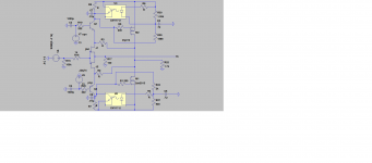
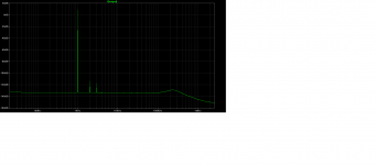
I connected the optocouplers to the amplifier as in this circuit to see what it would do. With the optocouplers first turned off the the distortion floor was flat across the bottom to about 200khz with about 400ma bias. Then I changed the resistors on the optos diodes until the bias reached about 60ma. As soon as the optos began to turn on it started to hump up at about 200khz but the THD (0.00009%) got better.
Attachments
Do you think a big cap 1000uF in parallel to R7 could lower your hump in a unimportant region?
Let us say under 5 Hz?
Let us say under 5 Hz?
I would not worry about that hump. Sometimes these things are artifacts of the LTSpice simulation. See what happens when you change the parameters used in the Transient_Analysis or the FFT. Make sure that all compression is turned off in the Tools/Control_Panel. Also make sure you are using double-precision floatinh point calculations by adding ".options numdgt=9" to your .asc file.
I had those settings already set but thanks Lynn. I have the same circuit but without the optocouplers and when I added .07uf caps to ground to the jfet side of the cascode resistors it acted different with each circuit. It created an ugly hump on the original circuit but only seemed to shifted the same hump down to 350khz on the opto circuit. This also lowered the distortion on the opto circuit to 0.00005%.
Last edited:

o.k. some news.....😀
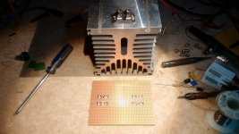
1. Friend Frank just does a draft for a experimental board with one optocoupler.
Big THXs Frank!
2. Meanwhile I tried to solve the problem with the stability of the second stage without degeneration inspired by Jeffs brute force intentions F7 like. I mounted instead of the SK/SJ the ALFs. My hope was that offset and bias behave like in my F7 clone very stable.
Indeed the bias was from beginning very stable at around 50mA, but the offset wandered ugly. After half an hour when the amp had the 45 degrees I am used to, it stayed fairly constant. I went to the dinning room where the speakers stand and the one side I measured had already again 8V.
I do not exactly know if the cooling down was the cause or something got loose in the amp.
3. I will try it again after installing a kind of thermistor for the J-fets or Toshibas mentioned here by Lynn and Rob and Jeff.
4. I do not know if without the 47R source resistors in the second stage the sound gets even more celestial....😀. Nevertheless compared to the effort we have to do to get the second stage working without degeneration I start to think..... really necessary?
5. but how does Nelson say ..."the shark must move on!"
.jpg")
Thanks 2 picoDumbs. What is the max supply voltage that I can safely apply to this output stage obviously it depends on the bias current?
In your version that we cannot wait to see the finished what bias are you running and supply volts? I currently run my F6 with around 1.8A and a supply of about 27V with 5U deluxe case and it it just warm. I'm going to assume the Hockey pucks can dissipate the heat better so can take a higher bias?
In your version that we cannot wait to see the finished what bias are you running and supply volts? I currently run my F6 with around 1.8A and a supply of about 27V with 5U deluxe case and it it just warm. I'm going to assume the Hockey pucks can dissipate the heat better so can take a higher bias?
- Home
- Amplifiers
- Pass Labs
- F4 Beast Builders