Concerning stability....
at least my "running at home" version with no source resistors at the J-Fets and at the pucks but with 47R at the sources of the SK/SJ
seems to show no oscillation.
10kHz around 4.5V/8 Ohm
I have not much experience in judging rectangles so tell me what you think, please.
😀
Looks very good.
Do it again at 100kHz.
It's looking great 2Pico! Do you have more pics to show us?
Give me a couple more weeks, and I'll post some more pics.
I haven't put the same effort into it as your project, but I'm happy.
Dear gentlemen,
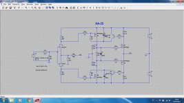
here is my humble contribution to the BEAST: As there shall be no degeneration I have found it mandatory to control both, the idle current of the toshiba - MOSFETs and the hockey - Pucks. So I developed the attached means for doing so. At least the sims show that it could be a working principle.
My amp has finished power supply and case work, the front - end is still missing.
Regards, Jürgen
Attachments
Thank you.
As a side note when I mentioned I thought the Hockey pucks ran hotter than either the IRF's and Crees this is not the case with correctly set up temperature compensation I had inadvertently wired up the pot backwards and was adjusting against the bias as it has a massive effect. Chased my tail but ended up with a really cool running amp albeit at a low bias of 800mA.
Can someone confirm the ideal bias is for the hockey pucks I think Generg said around 2 Amps?
Dear gentlemen,
here is my humble contribution to the BEAST: As there shall be no degeneration I have found it mandatory to control both, the idle current of the toshiba - MOSFETs and the hockey - Pucks. So I developed the attached means for doing so. At least the sims show that it could be a working principle.
My amp has finished power supply and case work, the front - end is still missing.
Regards, Jürgen
Very clever and minimalistic!
Can you tune it to work with 0R1 in the drains of the pucks!
Good morning,
at the moment dimensioning is like following: Idle 2A, 0R33 gives 0.66V for the bipolars. dissipation is approx. 1.3W per resistor. Using opto couplers instead (1V threshold) leads to 0R5 and 2W dissipation. I think you can go either way.
With 0.1R you would need some gain or a different kind of current mirror or current to voltage conversion to get it working which will make things more complicated as the signal is below one silicon threshold.
What is your reason using 0R1?
Regards, Jürgen
Dear gentlemen,
here is my humble contribution to the BEAST: As there shall be no degeneration I have found it mandatory to control both, the idle current of the toshiba - MOSFETs and the hockey - Pucks. So I developed the attached means for doing so. At least the sims show that it could be a working principle.
My amp has finished power supply and case work, the front - end is still missing.
Regards, Jürgen
Very nice and clever idea indeed!
...
With 0.1R you would need some gain or a different kind of current mirror or current to voltage conversion to get it working which will make things more complicated as the signal is below one silicon threshold.
...
Regards, Jürgen
How about using JFETs instead of bipolar transistors?
Thanks for the positive Feedback.
Using JFETs in order to accomplish the function is a way worth to consider. JFETs in contrary to bipolars are depletion-devices so the circuit has to be adopted for that and the thermal behaviour has to be taken into account. I`m very busy these days, but as soon as I`ll find time I think about an alternative solution using JFETs.
Regards, Jürgen
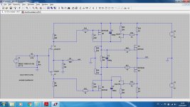
Here is the version using JFETs as suggested.
Basically it is working in the sims. But I think it is more critcal to parameters like drain-resistors of the JFETs in the FE, thermal considerations, Idss of the JFETs in the bias Circuit, Ugs of the toshiba MOSFETs and the involved resistors. At the moment I prefer the bipolar version because of ist simplicity - I dont want the bias to go crazy from 2A to let`s say 40A or so. Anyway I have to repeat the sims with components with lower Ugs like logic level mosfets in order to ensure the function. In the end we would like to have a reliable solution that can get away with some component variations.
Btw. the described technology of controlling the bias without degeneration could be used in combination with other FEs too. I`ve also tried a version with folded cascode and shunt feedback.
Time to tell you that this idea has been derived from an ayre V3 amplifier where this kind of control has been used to stabilize the output offset voltage in combination with a folded cascode front-end (FE).
Attachments
Very interesting circuit, like you when I get more time I might build this. Forgive my ignorance but what is the purpose of C3?
So the circuit is no newcomer....🙂)
The Ayre solution prefers the bipolars too?
And big thanks!
Now I suggest everybody of us builds another version, classic Sony II like, PR version 1, PR version two, Lynn double optocoupler version , genergs double opto at the JFets,
Lynns thermistor solution, ZM s still playing version, Jeff's brute force version, Pozo1992 bipolar an j-Fet version, needtubes version, formantjims version.....
Anybody else.....:--))
Later central meeting on an Atlantic isle, Mr. Pass is invited with his version and discussion and hearing.
I know I am an illusionist....:--))
How productive this thread got and who is the starting point......thank you Nelson from my side again.
Last edited:
Would the bjt circuit still work if you lowered the .33 ohm resistor to .1 ohm and then connected two resistors in series between ground and the bottom of the .1 ohm resistor. Then connect the bjt base between the two series resistors. Basically the moving the voltage a little lower because the .1 ohm resistor is to small.
I already have another version in the worksNow I suggest everybody of us builds another version,.
Would the bjt circuit still work if you lowered the .33 ohm resistor to .1 ohm and then connected two resistors in series between ground and the bottom of the .1 ohm resistor. Then connect the bjt base between the two series resistors. Basically the moving the voltage a little lower because the .1 ohm resistor is to small.
Sounds good make a spice for us please!
😀😀
..........
Lynns thermistor solution, ZM s still playing version, Jeff's brute force version, Pozo1992 bipolar an j-Fet version, needtubes version, formantjims version.....
Anybody else.....:--))
.......
.
Yes, RobLK version of course....😀😀
Very interesting circuit, like you when I get more time I might build this. Forgive my ignorance but what is the purpose of C3?
C3 serves for equal AC-voltages at each gate of the hockey-Pucks.
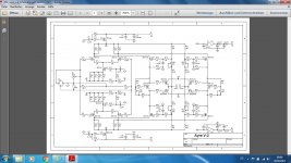
Attached please find the schematic of the Ayre V3 as found on the www.
Regards, Jürgen
Attachments
- Home
- Amplifiers
- Pass Labs
- F4 Beast Builders