.................
My wife is so tolerant at the moment, good times......:--))
''''''''''
That is only because she is planning a holiday!!! 🙂
😀
O.K. here we are. DC - testing done on both channels. Idle regulation works like simmed. Have to stop now. AC - tests follow after easter. Fortunately no poof.
Regards, Jürgen
Hi Jürgen,
I try to build your version on a perfboard too...
Only thing irritating me is two more BJTs that are not in your circuit.
Did you cascode the J-Fets?
Attachments
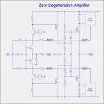
Here is a circuit topology that simulates well and whose bias at all stages is thermally stable without the using thermistors. It is unusual because of the negative feedback of the DC current through the output FETs to the JFET gates. The "secret" is in the design of bias circuit.
Attachments
if you are going to have dedicated bias circuits (in other words current sensing custom converters  ) ......... gate is last place where you need to push
at least for my logic
I have no doubt that everything behaves well in sims , but you know those gates ..... they can feel Sparrow flying 300m away ....
) ......... gate is last place where you need to push at least for my logic
I have no doubt that everything behaves well in sims , but you know those gates ..... they can feel Sparrow flying 300m away ....
I have not yet bench tested this circuit, so I do not know how it will behave in practice. The main reason that I considered feedback to the JFET gates was to reduce the thermal drift due to the temperature coefficients of the JFETS. The alternative of using negative DC feedback to the gates of the 2nd stage MOSFETs requires a bias circuit with much higher current gain and appeared to require a considerably more complicated bias circuit.if you are going to have dedicated bias circuits (in other words current sensing custom converters
at least for my logic
I have no doubt that everything behaves well in sims , but you know those gates ..... they can feel Sparrow flying 300m away ....
In the simulations of the thermal drift from 20C at power-on to 60C at operating temperature, only about 0.4uA variation of the DC feedback to the JFET gates is required to maintain the output stage bias current to within 20mA. That is a temperature coefficient of about 0.5uA/C.
It is such a fun to have pr and pozo1992 circuits as a background and to communicate with Lynn and ZM about different aspects of these ideas,
all this combined with all the elements Nelson gave us.....
combined in my brain to an Easter Egg, I did not expect myself.
😀😀😀
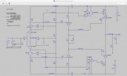
It shows at first glance a good behavior in LTSpice and possibly in real too.
No more opto couplers and thermistors and......and....
but only Nelsons good old cascode feedback to the first stage.. Because of PSSR it is possibly necessary to use TL431 for the J-Fet cascodes as in Sony II.
Oh my God, what a trip this thread.....may be someone has a Christmas Egg this year and the drama goes on, doesn't it Jeff.....?😀😀
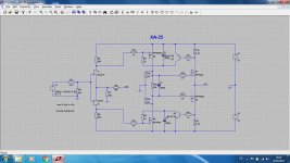
Here the circuit with the 0R33 resistors pozo1992 suggested.
all this combined with all the elements Nelson gave us.....
combined in my brain to an Easter Egg, I did not expect myself.
😀😀😀
It shows at first glance a good behavior in LTSpice and possibly in real too.
No more opto couplers and thermistors and......and....
but only Nelsons good old cascode feedback to the first stage.. Because of PSSR it is possibly necessary to use TL431 for the J-Fet cascodes as in Sony II.
Oh my God, what a trip this thread.....may be someone has a Christmas Egg this year and the drama goes on, doesn't it Jeff.....?😀😀
Here the circuit with the 0R33 resistors pozo1992 suggested.
Attachments
That is funny for me...
Changing the +/- voltage has nearly no influence on the OS and second stage bias, but the offset is very dependent from the +/- voltage.
Is this PSSR?
and Pozo1992 circuit is better in this aspect.
Changing the +/- voltage has nearly no influence on the OS and second stage bias, but the offset is very dependent from the +/- voltage.
Is this PSSR?
and Pozo1992 circuit is better in this aspect.
Last edited:
who cares what's it ....... and it isn't PSRR , more like inadequacy of servo mechanismus
base of which is of course part of LTP action
you know it's still not good enough
base of which is of course part of LTP action
you know it's still not good enough


is it foreseeable that a Beastly output stage might become well behaved and sufficiently reproducible that we could see boards and a BOM to enable other less sophisticated DIYers to build these F4 Beasts?
The noise performance you have achieved is impressive and the reduced parts count gives some potential to make this relatively simple to build..?
The noise performance you have achieved is impressive and the reduced parts count gives some potential to make this relatively simple to build..?
Oh my God, what a trip this thread.....may be someone has a Christmas Egg this year and the drama goes on, doesn't it Jeff.....?😀😀
Mr dumb dumb is in hybernation. I'll be back shortly.
Hi Jürgen,
I try to build your version on a perfboard too...
Only thing irritating me is two more BJTs that are not in your circuit.
Did you cascode the J-Fets?
I know I am late but those easter holidays in Venice....
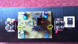
The components you encircled are the ZTX bipolars used for idle control, the other TO92 components in the picture are LM385`s (not shown in the schematic) to allow class AB mode - a trick stolen from the Firstwatt M2 schematic. Still left is a lot of data to be checked and tested.
I did not cascode the JFETs.
Sorry for the confusion caused.
Hi gents,
the circuit I`ve proposed has a poor disadvantage: It is interacting with the mechanism for the DC output offset voltage. The bias regulation circuit forms a loop within a loop and so should be much faster than the outermost loop which it is definitely not. So even more drawbacks. Basically the bias loop should neither interact with the DC offset loop nor the audio signal path.
In my setup the offset voltage is not very stable, it drifts around 50mV to 200mV even when warmed up which is not acceptable.
I`ll come back with an improved circuit.
one of things we often forgot to try in LTSpice is - to check sim at 10 or 15secs
make that a habbit
make that a habbit
one of things we often forgot to try in LTSpice is - to check sim at 10 or 15secs
make that a habbit
I've also found it useful to "pulse" the supply voltage from 0 to fully on for a couple seconds, then back to off to check for odd DC spikes at turn on and turn off. But, that already may be standard operating procedure for the rest of you.
Hi all,
slightly off topic but I see you guys here have made a lot of work around the IXYS FETs... here
I'm working on a P-channel CCS for a l'Amp based on the SJ28. I want to see if using one of the Ixys changes the distortion comapred to the IRFP9240 I am using now in the spice model. As it seems that the model posted in the Ixys site is not correct, would anybody here be willing to share the model for the IXTN40P50P? Thanks
- Home
- Amplifiers
- Pass Labs
- F4 Beast Builders