remember the tricks from BA3 FE ?
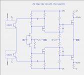
That might be a variation like this which doesn't have AC degeneration of the J313/K2013.
Attachments
looks good enough to me
and I'm pretty damn sure that Pa is not wasting time practicing our level of (over)engineering

and I'm pretty damn sure that Pa is not wasting time practicing our level of (over)engineering
ZM: Have you had a chance to listen to a "real" XA25? With the obscenely low levels of distortion shown in the XA25 User Manual, would it sound overly neutral, or would it allow the speakers, room, and of course, the musical material to define the sound?
nope
those which already arrived in OPLDF were damaged in smuggling (from factory) operation
my source told me that Wayne almost caught glimpse of white van back doors
Dennis is da man to ask - he's having real one , and few decent DIY FW ones to compare with
I didn't get impression that he for a moment started re-thinking decision to put up some greenies for it ....... to quote him - great dynamics and clarity
and - I'm saying again , as illustration - fave amp of my AR2 is Babelfish J2 ...... mine is M2 (even if BJ2 is better ) ....... but I'm wrong person for questions like these , simply because I'm always leaning to sound of (modern made) GrandMa's Telefunken radio console ......
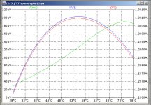
and , while we are at it ....... every darn possible simulation of concept is showing same thing - resulting from nature of outputs (it seems N are always having higher xconductance than P ones) - even if levels are obscenely low , 2nd is always dominant above 3rd and we have nice THD spectra as prescribed in yore J.Hiraga papers
One of the papers that has been of interest to me is Borbley's "JFETS: The New Frontier, Part 1", particularly figure 3B.
One of the papers that has been of interest to me is Borbley's "JFETS: The New Frontier, Part 1", particularly figure 3B.
.... and with CFB you can push toward possitive bias, what will additionaly stabilize BL part.
Scaling the power level
Now that we understand some approaches to building a stable amp with no degeneration and having one pair of common drain output FETs, I pose the following challenge: How do we scale the power up to 200W/CH or more? I see two options:
Forced air cooling of a single pair of output FETs at the higher power levels using a heat-tunne.
Multiple pairs of output FETs with a drain current sense resistor and servo for each output FET.
There are problems with each approach. I am not sure the the multiple servo approach can avoid undesirable servo interactions.
Any takers?
deja vu ...... and I can't remember from where it is
just take stereo amp , then bridge it and x-it as BA3 Bal
play with local and global feedback amounts to set THD spectra
or is there something more logical ?
just take stereo amp , then bridge it and x-it as BA3 Bal
play with local and global feedback amounts to set THD spectra
or is there something more logical ?
Yup, bridging two 50W @4R amplifiers (XA25) that will take you to around 100W @8R. How do we get to 200W or more? How much power per FET with a SOT-227 footprint can we dump into a convection cooled heatsink? I guess I need to run the the thermal convection heatsink simulator NatSink NatSink to get some estimates.
Yes. 200W or more. I am thinking of a design that would extend to the highest power levels of the XA.5 and XA.8 series amplifiers.200w/8ohm Class A?
all roads lead to Rome
though , that Rome , I'm not so interested in
just an idea - tried more than few times - common FE , multiple output stages
then do with them what you want
find simple enough and elegant way of biasing one vertical pair , then put zillion in parallel
not necessary to have drain current senses as part of CRC ........ or you can even have big C then separate (smaller) rc cells per each vertical pair
really ...... more than few possible choices
One pair of mosfet should be enough for that power with forced cooling.
I dont know how much you can reduce bias, because of class A envelope.
150w disippation per mosfet, or more ,seems to be possible with forced cooling.
In that case (non bridged), small CL voltage gain start to be unpractical.
I bet that amplifier is stable with given gain and amount of feedback, but I doubt that we can easy increase OLG and keep stability.
I dont have prototype in front on me, just talking....🙂
Attachments
How about a single temperature stabilized FE with each output FET having a thermistor on the spare source terminal to stabilize the FET current to reduce current hogging? It will not be perfect but perhaps adequate.

- Home
- Amplifiers
- Pass Labs
- F4 Beast Builders