
Why cant we just do something like this for the output?
ytes , we can
it works even better with 100R instead of 0R94

ytes , we can
it works even better with 100R instead of 0R94
Wouldn't that give us 13mA vs 1.3amps?

Dear Hockey players (or perhaps `Happy Puckers'?),
A lot of the early discussion was on the choice if the right pairing of devices. Later the conversation and development became centered around second harmonic versus high orders and spectral signature.
Would it simplify things to build a Beastly BA-1 single ended variant as this will remove at least one of these dilemmas?
Beardy
Another design goal at the start was the elimination of source resistors in every stage. The stock BA-1 design would require source resistors to establish bias for the output stage. But, you could always experiment with the idea to see how it turns out.
Yes, we've seen several for the complementary output stage. Now that I think about it, I worked on a version of a quasi-complementary (~"single-ended") output stage which did not include source resistors back before Pass confirmed that the output stage of XA-25 is complementary. My results in SPICE were promising, but I never built the amp.
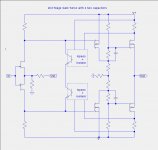
I have a question about bias servos. In the figure below I show idealized schematics for a 3-stage CFA without any servos, with a single servo, and with a pair of independent servos. Most of the bias circuits in this thread of are of the single servo variety. Not shown is the low-pass filtering needed to eliminate most of the AC component of the vistage across the drain sense resistors.
The question is whether the pair of independent servos will have "dualing servo problems" where there is an oscillation (motorboating) between them. My background does not contain a very good understanding of control theory which addresses problems like this.
Can anyone respond?
The question is whether the pair of independent servos will have "dualing servo problems" where there is an oscillation (motorboating) between them. My background does not contain a very good understanding of control theory which addresses problems like this.
Can anyone respond?
Attachments
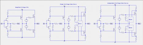
one servo with 2 senses or two servos connected in series , is there practical difference?
however , your third picture - they aren't connected in series , and that's big nono , at least in my book , titled - Book of all prices which I paid , in little service room
disclaimer - not exactly that I have special knowledge in servos
however , your third picture - they aren't connected in series , and that's big nono , at least in my book , titled - Book of all prices which I paid , in little service room
disclaimer - not exactly that I have special knowledge in servos
The situation is actually more complicated. There is also the global feedback loop to the JFET sources.
In various commercial products, such at John Curl's Blowtorch preamp and preamps by others, there is a bias servo combined with an output offset servo, as well as a global feedback loop.
In various commercial products, such at John Curl's Blowtorch preamp and preamps by others, there is a bias servo combined with an output offset servo, as well as a global feedback loop.
yup
agree on that
at least , that's the way how we are looking at XA25 puzzle
there is certainty that Pa is having some nasty twist , here and there ...
agree on that
at least , that's the way how we are looking at XA25 puzzle
there is certainty that Pa is having some nasty twist , here and there ...
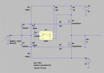
What went wrong? I have gone all to the way left with a BJT based servo on the JFET gates that simulated well. You didn't seem to like that one either. Post #925 http://www.diyaudio.com/forums/pass-labs/300233-f4-beast-builders-93.html#post5049646
if you are going to have dedicated bias circuits (in other words current sensing custom converters
 ) ......... gate is last place where you need to push
at least for my logic
I have no doubt that everything behaves well in sims , but you know those gates ..... they can feel Sparrow flying 300m away ....
at least for my logic
I have no doubt that everything behaves well in sims , but you know those gates ..... they can feel Sparrow flying 300m away ....
well , you can't go to sources with servo , you need them for NFB
I don't like gates
what's left ?
(of electrodes/pins?)
I don't like gates
what's left ?
(of electrodes/pins?)
well , you can't go to sources with servo , you need them for NFB
I don't like gates
what's left ?
(of electrodes/pins?)
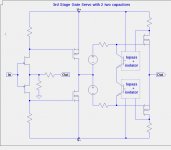
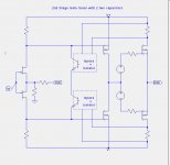
All that is left are the nodes between the JFET drains and the cascode BJT emitters.
I didn't show the whole circuit in post #956:
Attachments
- Home
- Amplifiers
- Pass Labs
- F4 Beast Builders