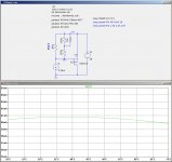
Here is another approach for stabilizing the FE FET bias current using a thermistor rather than using the optocoupler bias circuit. The schematic is shows the relevant piece of the FE circuit, where R1 is the bias adjustment pot, and R2, R3 and NTC are the added components for the thermistor stabilization of the bias current vs. temperature.
Attachments
and the same procedure for the SK2013?
It's the same deal as F5 brother.
Nothing new.
My thermistor circuit did not include the JFET and its associated temperature coefficient, which makes things considerably more complicated.
Here is another approach for stabilizing the FE FET bias current using a thermistor rather than using the optocoupler bias circuit.
This is what I was planning to use, although I was a little ashamed to mention it since the thread seemed to be trending toward rather elaborate means of controlling bias...
Looks like my build is on hold at least until summer, though.
It's the same deal as F5 brother.
Nothing new.
Not quite. The F5 circuit did not have a resistor in parallel with the thermistor, which is important for linearizing the thermistor behavior.
Not quite. The F5 circuit did not have a resistor in parallel with the thermistor, which is important for linearizing the thermistor behavior.
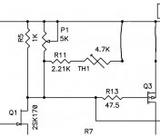
Of course. The idea is the same though. Look at F5 Turbo, you have a resistor in series and in parallel with the thermistor.
The correct resistor values and arrangement will depend on the thermal coefficient of Toshiba mosfets as you would already know. 🙂
I always claim Papa used his time machine to steal my ideas. 😀
Last edited:
From F5 Turbo, simply delete the degenerating resistors R17 and R18 and you have the modified circuit.
The principle is the same the resistor values/arrangement may need to be different.
The principle is the same the resistor values/arrangement may need to be different.
Attachments

Last edited:
From F5 Turbo, simply delete the degenerating resistors R17 and R18 and you have the modified circuit.
The principle is the same the resistor values/arrangement may need to be different.
There is still no resistor in parallel with only the thermistor.
There is still no resistor in parallel with only the thermistor.
Like I said the arrangement may need to be different to correctly compensate for the thermal coefficient of the mosfet.
I'm not picking on your idea, just pointing out to Generg that the idea is already proven and will certainly work.
2picoDumbs shows me the way......
😀
Maybe I go first the adventures route
and later the proven one.....🙂🙂
😀
Maybe I go first the adventures route
and later the proven one.....🙂🙂
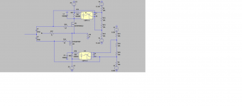
To get the optocoupler in the outputstage is an interesting task.
But without source resistors it is difficult to get the voltage for the LED.
Maybe the optocoupler is not so important in the OS but in the second stage where the thermal runaway is more present.
As far as I can say Lynn and me will do an optocoupler for the second stage in real soon.
And of course Jeff will come out with his brute force solution also soon. I am already eager to see what he will do.
yes , that's logical and best ......
however , I wouldn't use more than 0R1 there
I did use that size resistor and smaller but I had to use some op amps between them and the optos. That's the reason I used the op amps. I just didn't want to use so many parts. Also I don't know if it measures as well as this circuit. For some reason I had it in my head that much resistance wasn't to big.
- Home
- Amplifiers
- Pass Labs
- F4 Beast Builders