4.5" rumour I inadvertently started ;-)
Sorry I meant the 4" driver. I am very interested in this driver as a mid going down to about 120hz and crossing to maybe a 10" sub, all in sealed enclosures.
Sorry I meant the 4" driver. I am very interested in this driver as a mid going down to about 120hz and crossing to maybe a 10" sub, all in sealed enclosures.
Build 1
mainframe99
Volume: ?
Build 2
Norman Tracy
Volume: 16L PR
Build 3
xrk971
Volume: ?
Build 4
jmpsmash
Volume: ~21L
Build 5
mainframe99
Volume: ?
Build 6
xrk971
Volume: ~25L TL
Build 7
mainframe99
Volume: ?
Build 8
tktran303
Volume: 19.5L Ported
Build 9
Norman Tracy
Volume 25L PR
Apologies for my absence, things are still cooking here but slowly as life is getting in the way.
First build was 15L ported. Port area too small
Second build was 22L dual PRs. Too much volume
Third build - 17L ported with 1/4wave trap floorstander - still in production
Fi25v1 Investigations and Discussions
Further follow up on Dr. Lars Risbo’s comments on PRs (Passive Radiator) in post 745 I revisited my simulations in WinISD. Newly aware that when using PRs their in-box Fs shifts with the enclosure volume I now note the sim tool reports this when using PRs. The sim shows a 25 L box with two PTT6.5PRs shifts in-box Fs to 30 Hz. Model a vented version with a 30 Hz vent and it shows a similar response peak circa 33-35 Hz as the Fi25v1. Dr. Lars’ recommendation to go with a vent in 25 L enclosure looks all the more attractive because that curve has a less sharp peak and the valley droop between 35 – 100 Hz reaches –2.5 dB vs. –3.5 dB on the PR tuned version. Taken as a single number the 1 dB difference does not sound like much, on the graph it is quite a bit more area under the curve spanning 30 – 100 Hz. Changing the 25 L vented version tuning to 25 Hz and one gets exactly the same curve as the ‘Fi EBS –3’ sim on the graph I posted above. A very similar result is obtained adding 100 grams to the two PRs in Fi25v1. The difference between ported & PR is a faster roll off below 25 Hz with the PRs. Running such sims I have often wondered about the trade off of deeper response (in this case into the 20s) Extended Bass Shelf offers at the expense of much higher –3 dB point. In a vented Fi25v2 this can be explored by preparing vent tubes tuned to both 30 and 25 Hz.
We should be cautious with the enclosure volume discussion not to lose sight of the damping, i.e. total system enclosure + driver resulting Q, side of the equation. Citing Hificompass’ work in post 748 nanou64000 touches on this “20 liters it becomes very deep, but sluggish, and at 12 liters it is already dry”. We had a similar experience last Thursday with my listening group when I demo’ed the Fi16v3 varying the mass loading of its SB Acoustics 5”x 8” SB15SFCR-00 PR. First trial was with 100g added mass on the PR. Sounded Purifi-great with nice deep bass. Second trial removed added weight reverting to PRs default tuning. It was immediately apparent no added mass on SB 5”x 8” PR in the 16L box is the preferred tuning. Bass was tighter and more transparent, what I did not anticipate is how much cleaner and more open the midrange became.
Staring with post 747 an excellent discussion occurs on how with quite a few designs having been accomplished what the good enclosure volumes for PTT6.5Ws. While remaining open to the larger volumes I explore in the Fi25v1 to anyone reading this perhaps a bit confused I certainly agree with 14-16 liters as nanou64000 writes in post 748 is the safe bet to build once and be done. If interested in a bit of experimenting as Haze Head is complementing 20 L then one can always measure up some wood blocks to take up some volume and 20 L on the outside becomes 16 L on the inside.
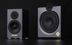
Onslo’s system in post 750 is very nice indeed. As a lover of high end monitors featuring such careful design and detailing all the kudos to Onslo. To call out just one detail note the integrated stand with the speaker wire connection on the base. And of course the casual “so I built some sealed aluminum enclosures”. The Purifi PTT6.5Ws plus dual 15” subs will certainly be a done and happy for quite awhile solution. While I have concentrated on the stereo monitor architecture exploring how Purifi “truly cracks the extended-stroke code” bi-amped with stereo subs has its attraction. The first party trick of the Purifi PTT6.5W is certainly how the bass depth and output capabilities punch will above their weight class. In his implementation Onslo plays to the driver’s other, arguably more important, strengths. That is of course the very low audible distortion and dynamic life.
Further follow up on Dr. Lars Risbo’s comments on PRs (Passive Radiator) in post 745 I revisited my simulations in WinISD. Newly aware that when using PRs their in-box Fs shifts with the enclosure volume I now note the sim tool reports this when using PRs. The sim shows a 25 L box with two PTT6.5PRs shifts in-box Fs to 30 Hz. Model a vented version with a 30 Hz vent and it shows a similar response peak circa 33-35 Hz as the Fi25v1. Dr. Lars’ recommendation to go with a vent in 25 L enclosure looks all the more attractive because that curve has a less sharp peak and the valley droop between 35 – 100 Hz reaches –2.5 dB vs. –3.5 dB on the PR tuned version. Taken as a single number the 1 dB difference does not sound like much, on the graph it is quite a bit more area under the curve spanning 30 – 100 Hz. Changing the 25 L vented version tuning to 25 Hz and one gets exactly the same curve as the ‘Fi EBS –3’ sim on the graph I posted above. A very similar result is obtained adding 100 grams to the two PRs in Fi25v1. The difference between ported & PR is a faster roll off below 25 Hz with the PRs. Running such sims I have often wondered about the trade off of deeper response (in this case into the 20s) Extended Bass Shelf offers at the expense of much higher –3 dB point. In a vented Fi25v2 this can be explored by preparing vent tubes tuned to both 30 and 25 Hz.
We should be cautious with the enclosure volume discussion not to lose sight of the damping, i.e. total system enclosure + driver resulting Q, side of the equation. Citing Hificompass’ work in post 748 nanou64000 touches on this “20 liters it becomes very deep, but sluggish, and at 12 liters it is already dry”. We had a similar experience last Thursday with my listening group when I demo’ed the Fi16v3 varying the mass loading of its SB Acoustics 5”x 8” SB15SFCR-00 PR. First trial was with 100g added mass on the PR. Sounded Purifi-great with nice deep bass. Second trial removed added weight reverting to PRs default tuning. It was immediately apparent no added mass on SB 5”x 8” PR in the 16L box is the preferred tuning. Bass was tighter and more transparent, what I did not anticipate is how much cleaner and more open the midrange became.
Staring with post 747 an excellent discussion occurs on how with quite a few designs having been accomplished what the good enclosure volumes for PTT6.5Ws. While remaining open to the larger volumes I explore in the Fi25v1 to anyone reading this perhaps a bit confused I certainly agree with 14-16 liters as nanou64000 writes in post 748 is the safe bet to build once and be done. If interested in a bit of experimenting as Haze Head is complementing 20 L then one can always measure up some wood blocks to take up some volume and 20 L on the outside becomes 16 L on the inside.
Onslo’s system in post 750 is very nice indeed. As a lover of high end monitors featuring such careful design and detailing all the kudos to Onslo. To call out just one detail note the integrated stand with the speaker wire connection on the base. And of course the casual “so I built some sealed aluminum enclosures”. The Purifi PTT6.5Ws plus dual 15” subs will certainly be a done and happy for quite awhile solution. While I have concentrated on the stereo monitor architecture exploring how Purifi “truly cracks the extended-stroke code” bi-amped with stereo subs has its attraction. The first party trick of the Purifi PTT6.5W is certainly how the bass depth and output capabilities punch will above their weight class. In his implementation Onslo plays to the driver’s other, arguably more important, strengths. That is of course the very low audible distortion and dynamic life.
Thanks Norman, There is still a lot of tweaking.
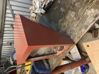
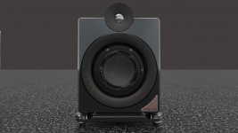
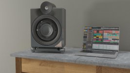
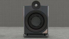
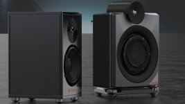
I made them in a way I can bolt on various baffles as I have several tweeters to try. As the image shows my first baffles were not even asymmetric left and right as I was too lazy to draw two files and itching to try them so routed two lefts (I am lucky enough to have a CNC router so can easily nock up another iteration).
I also am fairly convinced that sealed subs will integrate better than my current ported subs. I am researching suitable drivers now and will build a similar rolled aluminium housing for them. Suggestions?
As you rightly say I am throwing away one of the highly valuable traits of this driver (its incredible extension) and I am not certain that I should not take it lower in a larger enclosure. However the ported experiments I first did resulted in certainly deeper bass, but nothing like the clean and tight sound I get in this small sealed enclosure.
Has anyone done any detailed modelling or experiments of various sealed volumes for these drivers?
Attachments
On PRs
For my designs it comes down to cost vs. performance tradeoff with some styling and enclosure architecture considerations folded in.
The short answer is I believe for ultimate performance the revolutionary constant area surround and highly engineered soft parts make the PTT6.5PR worth the cost. Ideally a pair of them. In the Fi16v3 I am exploring a lower cost speaker featuring the PTT6.5W and therefore specified the SB 5” x 8” PR. A lesson in sometimes one has to build and listen because while the 5x8 is considerably down on displacement capability in the real world it is providing very satisfactory performance.
That summary should suffice, but then I went all spread sheet as seen in the attached image. These are the likely candidates from Madisound’s present stock. By considering the piston area and Xmax and number of PRs in a given box one sees the total displacement volume a given solution offers. All specs are manufacturers’ ratings. This reminds the maths (please think ‘maths’ with an English accent) count so larger Xmax helps and diameter increases really help thanks to radius getting squared in the area equation.

In the chart line 2 is my Fi16v1 and line 3 the Fi16v3. The 10x cost delta shows going all Purifi certainly exemplifies how in high-end HiFi the cost benefits curves can go exponential. Lines 4 & 5 show it takes 2 or 3 of the SB 6” to keep up. I find the solution on line 6 rather interesting, two of the SB 8.5” getting a lot of displacement for only $75.
Disclaimer – This spreadsheet focuses on achieving the desired displacement volume and the costs to get there. No effort made at this time to analyze the T/S parameters of PRs lines 4 – 16 to determine if they are suitable for use with Purifi PTT6.5W. That exercise, as professors like to say, is left to the student.
just wonder why most people are thinking single passive radiator instead of using dual (e.gSB Acoustics SB16PFCR-00 ) ? is dual harder to implement when weight is taking into account ?
I think most ppl are actually using 2 PRs.
For my designs it comes down to cost vs. performance tradeoff with some styling and enclosure architecture considerations folded in.
The short answer is I believe for ultimate performance the revolutionary constant area surround and highly engineered soft parts make the PTT6.5PR worth the cost. Ideally a pair of them. In the Fi16v3 I am exploring a lower cost speaker featuring the PTT6.5W and therefore specified the SB 5” x 8” PR. A lesson in sometimes one has to build and listen because while the 5x8 is considerably down on displacement capability in the real world it is providing very satisfactory performance.
That summary should suffice, but then I went all spread sheet as seen in the attached image. These are the likely candidates from Madisound’s present stock. By considering the piston area and Xmax and number of PRs in a given box one sees the total displacement volume a given solution offers. All specs are manufacturers’ ratings. This reminds the maths (please think ‘maths’ with an English accent) count so larger Xmax helps and diameter increases really help thanks to radius getting squared in the area equation.
In the chart line 2 is my Fi16v1 and line 3 the Fi16v3. The 10x cost delta shows going all Purifi certainly exemplifies how in high-end HiFi the cost benefits curves can go exponential. Lines 4 & 5 show it takes 2 or 3 of the SB 6” to keep up. I find the solution on line 6 rather interesting, two of the SB 8.5” getting a lot of displacement for only $75.
Disclaimer – This spreadsheet focuses on achieving the desired displacement volume and the costs to get there. No effort made at this time to analyze the T/S parameters of PRs lines 4 – 16 to determine if they are suitable for use with Purifi PTT6.5W. That exercise, as professors like to say, is left to the student.
@Norman Tracy,
Continuing with professorial sayings. "That's a handy lemma you have there." Handy spread sheet that is.
One thing I'm not quite picking up is the significance of the PR XMAX. To my mind the max displacement of a PR, or multiple PRs can only equal that of the driver. With our PTT6.5 concerns, if we double the surface area, i.e. dual Purifi PRs, or a single 8" or 10", the PR cone travel will necessarily be reduced in proportion to the increased PR surface area. In other words, dual Purifi PRs will have their throw reduced by half. A balloon analogy comes to mind; take one filled balloon of a given size and force it to displace into a Tee connecting two empty balloons of the same size. Ensuring that the PRs XMAX can handle the unusual throw of the PTT6.5 makes sense to me. What you describe sounds more like PRs amounting to a larger surface area actually travelling the same distance as the driver. Or am I misinterpreting?
@mainframe99, thanks for the updated specs. I'll add them-
Haze Head commented “not quite picking up is the significance of the PR XMAX. To my mind the max displacement of a PR, or multiple PRs can only equal that of the driver”. This is not so much “misinterpreting” as not taking the analysis far enough.
The balloon analogy is correct at or near DC steady state case. The woofer + enclosure +PR or vent (when present) system operates as an AC system subjected to changing frequencies and amplitudes. As Thiele and Small led us to understand the dynamic behavior of our speaker’s bass system can be explored by analyzing the physical and electrical characteristics when subjected to a range of frequencies and amplitudes. Among those physical properties we find weights and springs. Weights of the cone assemblies and air in the enclosure. Springs including the cone assemblies’ surround and spider and air compressing in the enclosure. Such mass + spring systems exhibit a characteristic known as ‘reactance’ where they store energy at one point in time then release it at another. When the system is at a point the reactive store – release cycle happens very efficiently because the masses and springs involved are in greatest sympathy that is the resonance frequency (Fs) we so often refer to in woofer + enclosure system design. Recall that at Fs the spring forces (compressing air in enclosure + PRs or air mass in vent tube) are high and holding the woofer very tightly. Or more accurately exerting maximum force on the woofer opposing its movement. Also at Fs the reactive energy exchange is very efficient at pushing energy into the vent or PR(s). That is why at Fs the woofer’s cone is barely moving while the PR(s) are pumping in and out like mad or the air in the vent tube is rushing in/out at its maximum velocity. In the balloon analogy it’s a linear system with 1:1 ratio between balloons, with reactive effects in play the ratio becomes something like 1:2 at the worst case point of Fs. Thus the design guideline PR displacement ideally approximately twice that of woofer’s capability if one wants maximum output.
In my spreadsheet I calculated displacement (cone area x Xmax) to account for the actual mechanism doing the work. It is tempting to focus on just the cone area of the woofer vs PR but how much air each can move is related to both cone area and stroke. Look at various PR data sheets for long and one sees just like woofers they vary in Xmax quantity (and quality, harder to see in a data sheet) so a more complete analysis accounts for both.
Thank you for that elaboration, it makes sense. With audio related stuff I've learned to not be surprised about the complexities involved 😀
So it's something like a spring with an almost stored hysteresis like energy acting on it. The fact that a PR system is sealed puts me, incorrectly, into a hydraulic system mindset. However, air being so compressible/vacuable??? is basically allowing for the PR to act as if punched with greater energy than the basic displacement would have done. Not sure if that is quite inline with the phenomenon you describe, but at the very least I can see reasons for the PR being more energetic. And come to think of it, the few PRs I've seen in action did really boogie.
I had been contemplating doing a custom PR fabrication that would integrate with the rear panel. More in depth PR discussions on this thread inspired further ideas about a front baffle PR; of course now I can see that the XMAX variable may create some problems for the concept. Back to the o'l drawing computer--but trying stuff is half the fun anyway-
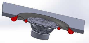
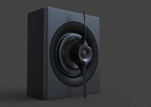
Concentric PR Concept
Here's the idea I was playing around with. The driver is actually suspended via a basket to the baffle, similar to how the speaker's own basket looks. I left that out for a simpler view of what I want to do. There are probably a number of reasons against such a configuration, but there also appear, at least on the surface, to be solutions for most issues I'm aware of. Admittedly there is more that I am unaware of than aware of. The driver can be internally baffled if that is required. Spider suspension can be employed if that matters, and so on. The surrounds could be flipped upright and because I'm considering polyethyl, it should be diffraction friendly. The mass is highly controllable, anywhere from very light to what ever mass is preferred. Then again, I've not seen this done so maybe there is some unwritten rule about why....
Here's the idea I was playing around with. The driver is actually suspended via a basket to the baffle, similar to how the speaker's own basket looks. I left that out for a simpler view of what I want to do. There are probably a number of reasons against such a configuration, but there also appear, at least on the surface, to be solutions for most issues I'm aware of. Admittedly there is more that I am unaware of than aware of. The driver can be internally baffled if that is required. Spider suspension can be employed if that matters, and so on. The surrounds could be flipped upright and because I'm considering polyethyl, it should be diffraction friendly. The mass is highly controllable, anywhere from very light to what ever mass is preferred. Then again, I've not seen this done so maybe there is some unwritten rule about why....
Attachments
Ka – B O O M. Mind blown.
First off kudos on the 3D modeling skills. SolidWorks, Fusion 360, or ??
Next I am not sure if the correct comment is:
1. That will never work
2. Take down your render before too many people see it and file for a patent.
If you have the means, skills, and passion I say go for it.
First off kudos on the 3D modeling skills. SolidWorks, Fusion 360, or ??
Next I am not sure if the correct comment is:
1. That will never work
2. Take down your render before too many people see it and file for a patent.
If you have the means, skills, and passion I say go for it.
Wow Haze Head, that is a truly different idea.
I feel the same as Norman, part see's it as 'simply going to waste a heap of the drivers energy' and part 'this could be really effective'. The physics are a bit above my knowledge so I will be following others thoughts and your experiments with interest.
I also wonder if you should have some IP protection quickly just in case you've cracked the 'long driver mounting stroke code'.
Now comes that moment of confession that I didn't model the PTT driver lol! You can download it from Purifi, fyi. I'm both happily and painfully aware of this as I'd already spent many an hour modeling that surround and even have it available for download on the software forum. Solidworks and in the case of organic shapes a plugin called Powersurfacing are the modeling tools and I render in Keyshot.
Facing your prognosis of a concentric PR build, I'll have to weigh some options about how to proceed. One thing I really liked is the ability to stay very compact without a rear firing PR, and hence no wall proximity issues. Also, having learned of your out of phase/distance trouble, it seemed reasonable that direct alignment would be the most uniform position as far as how direct the suspension is loaded.
The Magico A1 is a reference for where I want to get in terms of build execution, so I have done a fair amount of modeling and comparing of that piece.
As to the patent.... nah, It's now safely in the world of prior art for us open sourcers 😉 If only it would do what's intended of it, but that's a whole different deal. It may be the perfect frisbee?
EDIT: I also added the original version with flat PR cone and upward facing surround for a sense of the many ways this can be configured.
Attachments
Last edited:
Wow Haze Head, that is a truly different idea.
I feel the same as Norman, part see's it as 'simply going to waste a heap of the drivers energy' and part 'this could be really effective'. The physics are a bit above my knowledge so I will be following others thoughts and your experiments with interest.
I also wonder if you should have some IP protection quickly just in case you've cracked the 'long driver mounting stroke code'.
Thanks, Onslo! No worries, it's officially prior art now and I deem it to be open source for diy.
It sounds like you are thinking that the Purifi is sort of free floating, hence loosing energy. But it is actually attached to the baffle that bridges across the PR ring, so it stays in position as any typical driver would. In theory lol.
Ahhh now I understand.
Yes I see that working. Is cancellation more of an issue with 'short circuiting' occurring or I suppose the dampening will minimise that to a certain frequency too?
I love to see some out of the box thinking.
Yes I see that working. Is cancellation more of an issue with 'short circuiting' occurring or I suppose the dampening will minimise that to a certain frequency too?
I love to see some out of the box thinking.
I reckon it can be internally baffled as any other build would. The Driver can be in its own walled off tube until it reaches the rear and reflects back. The box is so narrow that you can maybe squeeze in one more reflection off the front again, and back before physically reaching the radiator. But I don't understand much of the sonic 'dark arts' and am more of a builder. In this case a concentric PR solves a lot of problems for me, like being compact, tidy, novel, etc. Making it worthy sound wise is rather a shot in the dark from my purview.
Perhaps off topic (or old news), but I note that Purifi is previewing a 6.5" midrange.
PTT6.5M04-NFA-01
The FR and distortion looks great until 3k or so. I will have to wait to see the off-axis response, but I wish they had come out with a PTT4.0M so beaming wasn't an issue. Perhaps they thought it more important to boost the efficiency.
PTT6.5M04-NFA-01
The FR and distortion looks great until 3k or so. I will have to wait to see the off-axis response, but I wish they had come out with a PTT4.0M so beaming wasn't an issue. Perhaps they thought it more important to boost the efficiency.
1 - Haze Head your concepts for a design with the coax passive radiator look fantastic. I am such a easy target for a really good render.
2 - On the topic of 20 Liter size towers for PTT6.5W Joseph Crowe has posted a blog including distortion measurements of his "1198" TL.
Purifi PTT6.5 Test Results in 1198 Transmission Line Enclosure – Joseph Crowe
1198 Floor Standing using Purifi PTT6.5W04 – Joseph Crowe
Plans or built units.
1198 Speaker Plans – Joseph Crowe
Speaker No. 1198 --- Floorstanding Transmission Line – Joseph Crowe
So 15 L is optimal for Purifi?
With an PR?
I know you talking a bit higher but for normal people?
With an PR?
I know you talking a bit higher but for normal people?
- Home
- Loudspeakers
- Multi-Way
- Exploring Purifi Woofer Speaker Builds