Hi
I would like to ask about the biasing of the amplifier, can you please explain to me how to determine the optimum bias current?
I know that you suggest a bias of 55ma but I was wondering what changes will I see to the output signal when i compare 2 different bias points, for example 5ma and 50ma, will this changes be visible in any input level or only to low level signals?.
Does this optimum bias come from the characteristics of the transistors or can it be determined with a signal generator and an oscilloscope, if this is the case then can you please tell me what signal to use (frequency and level) and what to look for in the output waveform.
Thank you
Alex
You can't really tell on a scope, you really need to use a distortion analyser. If you have a PC, RightMark will do the trick, but you will need a dummy load and a couple of resistors to make up an attenuator so the sound card only sees about 1V P2P.
pinkmouse said:You can't really tell on a scope, you really need to use a distortion analyser. If you have a PC, RightMark will do the trick, but you will need a dummy load and a couple of resistors to make up an attenuator so the sound card only sees about 1V P2P.
I'm already using my sound card as an oscilloscope (with a buffer/attenuator circuit) so there is no problem there and i can measure the THD too.
So you mean that bias changes only the THD of an amp and i should increase it until the THD stops decreasing?
Should this be measured when the amp is working full power or with a low signal?
Alex
Case
Helllllooo Mike 🙂
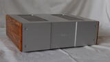
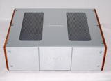
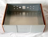
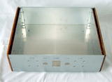
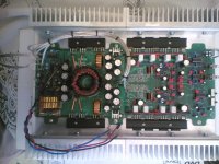
I havent been here for long time. Because I´m very bussy in school and on other important projects. But I must show you something. I hope that under our xmas tree will be new toy for thin boy. My friend from Slovakia made this nice thing for me. I can say that my Sym will be done under international cooperation on axis from Germany through Czech to Slovakia. I hope you´ll enjoy pictures.
Best regards
Karel


Helllllooo Mike 🙂
I havent been here for long time. Because I´m very bussy in school and on other important projects. But I must show you something. I hope that under our xmas tree will be new toy for thin boy. My friend from Slovakia made this nice thing for me. I can say that my Sym will be done under international cooperation on axis from Germany through Czech to Slovakia. I hope you´ll enjoy pictures.
Best regards
Karel


Re: Case
You have a talented friend. That is very Very nice work. A work of art.
Sheldon
Chuck911 said:Helllllooo Mike 🙂
I havent been here for long time. Because I´m very bussy in school and on other important projects. But I must show you something. I hope that under our xmas tree will be new toy for thin boy. My friend from Slovakia made this nice thing for me. I can say that my Sym will be done under international cooperation on axis from Germany through Czech to Slovakia. I hope you´ll enjoy pictures.
Best regards
Karel
/URL]
You have a talented friend. That is very Very nice work. A work of art.
Sheldon
That is very, very nice. When you're finished, I can see I'll have to give up my title for the prettiest Symasym! 🙂
Thanks guys. I must tell him. But he must be talented because work like this is his business and lifehood. 😉
Hi Chuck911,
Simply gorgeous! Your friend does wonderful work.
What lovely cabinets! Stunning work really. Mike, need a nicer Symasym to put in those boxes!!!!
-Chris
Simply gorgeous! Your friend does wonderful work.
What lovely cabinets! Stunning work really. Mike, need a nicer Symasym to put in those boxes!!!!
-Chris
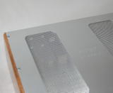
Be precise, Karel, and make front panel by thicker material, not by this sandwich...also make ventilation slots at downside... 😎
At least, Pavel, you could have found a bit of kind word before you started to advise ... 😉 - it is your style, I know. Maybe high time to think it over.
Very nice job, Karel!
And Upupa's advice regarding vent slots is right, in case that you need to spread more power.
Very nice job, Karel!
And Upupa's advice regarding vent slots is right, in case that you need to spread more power.
Pavel,
what's your arguement for a thicker frontplate, i'm not used to such advices from you ?
Over and Hoephoephoep.
what's your arguement for a thicker frontplate, i'm not used to such advices from you ?
Over and Hoephoephoep.
What argument, Jacco ? Design criterion - is nicer, when front panel ( if his thickness is visible ) have " correct " proportion to the size of enclosure.... Nothing new from me, ask some industry designer... 😎
UE: Be precise, Karel, and make front panel by thicker material, not by this sandwich...also make ventilation slots at downside...
Whith this sandwich sollution the case comes a little more expensive than a standard Fe black terrible rack case from shop. Dont be afraid if the down ventilation will be necessary it can be finished too. 😉
Chuck911 said:Thanks guys. I must tell him. But he must be talented because work like this is his business and lifehood. 😉
Is he looking for more work?
Is he looking for more work?
Why are you asking? Do you need some metalwork?
Upupa Epops said:proportion
Pavel,
you didn't respond to the Upupa Epops love call.
(they call it a Hop overhere, next time i'll adress you formerly😛avel Hop)
Funny, Karel's creation made me think of Tom Colangelo's Performance boxes.
I know i was really attracted by the Cello looks back then, so much different from the regular bulky yanks, and with really thin front panels. (current stuff like the P-labs X models are a bit grotesk, imo)
Second attempt: Hoephoephoep.
- Home
- Amplifiers
- Solid State
- Explendid amplifier designed by Michael Bittner, our MikeB