I used the little Aurasounds in the past. i think they are underhung radial magnet type motors. that means there is a steel yoke.
It looks like I may have misunderstood the marketing blurb I read a few years ago. They appear to have a unique design, with one side of the rare earth ring magnet directly adjacent to the outside of the voice coil, but there is a ferrous cup and pole piece that I didn't notice. Thanks for the correction. There are diagrams in this pdf

https://www.parts-express.com/pedocs/tech-docs/Aurasound-NRT-Whitepaper.pdf
https://www.parts-express.com/pedocs/tech-docs/Aurasound-NRT-Whitepaper.pdf

Well now that the original poster has been deleted, what were we talking about again?
Is there anything we have nailed down in this discussion that would help us make better speakers?
Is there anything we have nailed down in this discussion that would help us make better speakers?
What happened?
THD seemed to get worse with current drive at low-ish frequencies. If mapped against the speaker's impedance curve, that also matches the bass impedance peaks if the slope extends out to 200-300Hz.
As for the striped blue graphs, I find them hard to interpret.
The THD improvements with current drive seemed consistent with the usual rising impedance that woofers have from about 500Hz and up.Is there anything we have nailed down in this discussion that would help us make better speakers?
THD seemed to get worse with current drive at low-ish frequencies. If mapped against the speaker's impedance curve, that also matches the bass impedance peaks if the slope extends out to 200-300Hz.
As for the striped blue graphs, I find them hard to interpret.
I only have theories of the reason and a short timeline of events. But all we can really do is make more speakers and see if he eventually returns, or posts on some other forum.
I think if we want to make progress though, what has been discussed up to now is sufficient. Current drive has difficulties, but they are all surmountable ones. If we use current drive on an already good driver then we get something almost as good as Purifi at a possibly lower price.
All the ingredients have been present for years on the forum for a current drive project, but no one has seen fit to simply go forward. Well probably some, but not that I can remember right this moment.
What happened?
The THD improvements with current drive seemed consistent with the usual rising impedance that woofers have from about 500Hz and up.
THD seemed to get worse with current drive at low-ish frequencies. If mapped against the speaker's impedance curve, that also matches the bass impedance peaks if the slope extends out to 200-300Hz.
As for the striped blue graphs, I find them hard to interpret.
Here's what happened.
1. The one guy that was doing all the work apparently got tired of getting shouted down by people making false assertions with nothing to back them up. Some folks spent lots of money and several years studying physics in high school and college complete with lots of hours performing lab experiments and writing lab reports so they have pretty high confidence in things like F = B * l * i.
For instance as described in the current drive of loudspeakers book: It's pretty well known that F = ma and F = b * l * i Force = field strength * length of wire * current in the wire. Solving for acceleration a and substituting in for Force acceleration a = b * l * i / m Now taking a wild leap into acoustics from basic physics and accepting that SPL is proportional to acceleration you see that SPL is proportional to current. Period. So many posts making assertions to the contrary were a waste of everyone's time.
Others have been arguing about things totally unrelated to the subject being discussed like current drive of multi-way speakers. So dogs have been barking at trains, and the trains just kept going.
1. part B. Voltage drive => low to zero output impedance. Current drive => short hand for a transconductance amplifier => very high output impedance. Why bother posting repeatedly pretending to be smart and also confused about this simple use of terminology.
2. Experiment design is complicated. You have to be able to isolate one source of distortion from all the others. As was mentioned many posts back, there's no point in comparing distortion graphs between voltage and current drive when the driver displacement in the two test hasn't been equalized first. Many of these graphs show higher SPL at low frequency for the current drive. Of course the distortion is higher when the motor has higher excursion. If the current drive was equalized using a Linkwitz transform at the line level, such that the SPL graph matched that of the voltage drive, then the comparison of the distortion levels would be meaningful. Without equalization the results are polluted and there is no way to know what effect is dominant. No conclusion can be made with any confidence.
3. I think a two tone test can be helpful to illustrate the benefit of current drive. A low frequency tone moving the motor such that the inductance is modulated there by amplitude modulating the higher tone when the speaker is using low impedance or voltage drive.
It would be great to see the thread continue with some others contributing more than just idle speculation and do some actual valid experiment design, make measurements and post them here. I built some multi-channel transconductance amplifiers a few years ago and may have documented some tests. Maybe I will be able to find some of those results or repeat the tests in the weeks ahead.
Designing speakers using the transconductance amps running individual drivers simply involved making an initial measurement and then applying the LInkwitz transform to produce the desired low frequency cut off and Q. For the midrange and tweeter drivers I would raise the cutoff frequency using the Linkwitz transform to create half of the fourth order LR crossover high pass filter. This works exceptionally well in my opinion.
For those who are wildly confident that what I said is wrong, read the books, go to office hours, do the lab, write it up and present your results here. I know, you can't sell a Transconductance amplifier in a HiFi store to drive a pair of three way speakers with parallel crossovers. That's not what we're talking about. Repeating what you "learned" reading Stereophile magazine, inch thick cables and super low impedance amplifiers "gripping" the woofer when the impedance of that woofer at resonance is a whopping 36 ohms, is not interesting to me.
I believe that both can be modeled easily using the WinISD software. There is an adjustable box leakage Q term if you click on the word Advanced on the box page. The Linkwitz transform is in the list of filters available to apply. This page seems to have good information regarding the use of resistive vents. I don't know if WinISD takes into account the acoustic output of the box leakage, so that seems important. Oh, and simply raising the value of Qe for the woofer will approximate running it with current drive in WinISD. I believe the amplifier impedance can also be changed to produce the effect as well.
This thread inspired me to do measurements of speaker current distortion when driven with a regular voltage output amp.
So toroidal current probes came into my mind that enable easy measurements even with full bridge amplifiers.
Magnetic probes are convenient, but performance specially in the sub audio region often is poor.
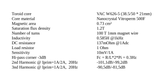
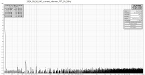
With some nice nanocrystalline toroids at hand waiting for an application I built a current probe that fits these needs.
So toroidal current probes came into my mind that enable easy measurements even with full bridge amplifiers.
Magnetic probes are convenient, but performance specially in the sub audio region often is poor.
With some nice nanocrystalline toroids at hand waiting for an application I built a current probe that fits these needs.
Attachments

Prior work on this forum:
But here too the originator soon gave up.
Loudspeakers are the most nonlinear elements in the whole audio reproduction chain and there are numerous ways to reduce their nonlinearity (as stated for example by Klippel here), including adoption of different types of acoustic, motion or electric feedback or machine learning. The most obvious and easiest to implement seems to be employment of current control instead of usual voltage control to drive the speakers. While trying to quantify the difference, I have written some MATLAB/Octave scripts aimed to automate and speed up comparative measurements of harmonic and...
But here too the originator soon gave up.
This thread inspired me to do measurements of speaker current distortion when driven with a regular voltage output amp.
So toroidal current probes came into my mind that enable easy measurements even with full bridge amplifiers.
Magnetic probes are convenient, but performance specially in the sub audio region often is poor.
With some nice nanocrystalline toroids at hand waiting for an application I built a current probe that fits these needs.
Hello bucks bunny ,
I like the idea of a current probe.
When you get down to it, that ferrite donut could have some "iron noise" issues all on its' own.
I am thinking of a current sensing series resistor.
I spent the weekend at Burning Amp 2024.
Scott Hinson did a very nice presentation about "cross overs". There were a couple of powerpoint slides that showed "iron noise" caused by iron laminate core coils. My brain did an Ah - Ha, I see "iron noise".
Thanks DT
Thanks for posting that. Unfortunately, like on so many threads, the originator didn't upload the matlab / octave scripts to this site, and the links are all dead now.Prior work on this forum:
Loudspeakers are the most nonlinear elements in the whole audio reproduction chain and there are numerous ways to reduce their nonlinearity (as stated for example by Klippel here), including adoption of different types of acoustic, motion or electric feedback or machine learning. The most obvious and easiest to implement seems to be employment of current control instead of usual voltage control to drive the speakers. While trying to quantify the difference, I have written some MATLAB/Octave scripts aimed to automate and speed up comparative measurements of harmonic and...
But here too the originator soon gave up.
Yes. For any given driver in a given enclosure (or more generally, a given acoustic loading) there is a source impedance vs. frequency profile that minimizes distortions and errors of any given kind as per whatever criteria you want to apply (a trade-off, like always). I've been writing that for many years now.Is there anything we have nailed down in this discussion that would help us make better speakers?
"Voltage drive" and "current drive" are just two of the simplest embodiments of such profiles among an infinite set. People have to understand that it's not voltage drive vs current drive as if that were the only two options.
I actually prefer the term effective termination impedance which includes the driver's own static impedance (which often is non-linear in various ways) which is in series with the external termination because it is that total impedance that counts.
There are no simple answers or shortcuts. Measure and listen are the only way.
Laboratory current probes like Tektronix A6302 + AM503 amplifier module include a Hall element path that handles LF and DC signals. Certainly one of the better investments for AM500 system owners.Magnetic probes are convenient, but performance specially in the sub audio region often is poor.
Full ack to your complete post but this tidbit is the most important one.2. Experiment design is complicated. You have to be able to isolate one source of distortion from all the others. As was mentioned many posts back, there's no point in comparing distortion graphs between voltage and current drive when the driver displacement in the two test hasn't been equalized first. Many of these graphs show higher SPL at low frequency for the current drive. Of course the distortion is higher when the motor has higher excursion. If the current drive was equalized using a Linkwitz transform at the line level, such that the SPL graph matched that of the voltage drive, then the comparison of the distortion levels would be meaningful. Without equalization the results are polluted and there is no way to know what effect is dominant. No conclusion can be made with any confidence.
I've used automated DSP (FIR) EQ to match frequency response of driver terminal voltage (or current, doesn't matter) to better than 0.1dB (1%) for being able to take out all the variables except for the effective termination impedances under test (see post #254 on that). Otherwise, measuring and listening results are useless.
Besides the price tag the question is their dynamic range. Such wideband devices are not very suitable for audio measurements.Laboratory current probes like Tektronix A6302 + AM503 amplifier module include a Hall element path that handles LF and DC signals. Certainly one of the better investments for AM500 system owners.
Last edited:
Yes I am aware of iron-related Barkhausen noise.When you get down to it, that ferrite donut could have some "iron noise" issues all on its' own.
This effect can easily be demonstrated by approaching some iron to the magnetic pickup of an electric guitar.
That is what I want to measure at real loudspeaker drivers.
Actually I built a 40dB low-noise pre-amp resulting in 4nV/sqrt(Hz) input noise with the probe connected.
And this noise floor does not rise when I apply primary current.
So I cannot see any intrinsic Barkhausen noise originating from that toroid.
I suspect Vitroperm F500 is still one of the best magnetic materials available on this globe
Attachments
Last edited:

Take a look at the attached link and the fabricated transformer shown.Yes I am aware of iron-related Barkhausen noise.
This effect can easily be demonstrated by approaching some iron to the magnetic pickup of an electric guitar.
That is what I want to measure at real loudspeaker drivers.
Actually I built a 40dB low-noise pre-amp resulting in 4nV/sqrt(Hz) input noise with the probe connected.
And this noise floor does not rise when I apply primary current.
So I cannot see any intrinsic Barkhausen noise originating from that toroid.
I suspect Vitroperm F500 is still one of the best magnetic materials available on this globe
A year or 2 back I made a similar donut transformer with I think that I remember Vitroperm 250F material and 43 some turns of CAT6 twisted pair wire.
I used my home brew transformer to measure noise injected into power supplies under test. The test transformer was every bit as good as the Bode brand injection transformer, still not hysteresis distortion free. Yes, past good enough.
https://purifi-audio.com/blog/tech-notes-1/this-thing-we-have-about-hysteresis-distortion-3
- Home
- Loudspeakers
- Multi-Way
- Experiments with the current drive