D
Deleted member 375592
As a continuation of work by Esa Merilainen and Pascal Brunet, as well as my previous work, an approach with a deeper feedback circuitry has been tested. The deeper feedback indeed lowers harmonic distortions by 20dB and more, including the most stubborn 3rd harmonic, in a somewhat unexpected (by me) way.

The driver impedance lump was modelled as Zeq = (L+RDC)||C||Rres:

Contrary to the statements of previous researchers, it was found that the p grade of Lp is neither 0.5 nor 0.55 but varies from driver to driver, from 0.6 to 1.0.


A reasonable amount of RF care was taken. The amplifier is stable. Measurements were taken by an 12dBA AudioTechnika 4040(Or 2020?) cardiod condenser microphone calibrated by ECM8000 calibrated by AZ8930, at 0.5m from the cone, while being adjusted to 1m loudness (60..85 dB SPL), in a moderately damped living room (RT60 ~= 250ms for f>200Hz). In the signal processing, frequency resolution was traded off to benefit precision and dynamic range (i.e. the curves have been denoised). Dotted lines correspond to the resulting noise floor for the given harmonic and excitation levels. The curves are positioned on the originating frequency, i.e. they correspond to the frequency that produces the harmonic, rather than where it appears, and are properly normalized for the cone frequency response (FR).


Note that an open-air inductor serves as an antenna and gets lots of interference, even after turning most of the switching PSUs in the vicinity off. In a real product, the inductor must be shielded.
If seen as necessary, the f<2Fs distortions can be dealt with by motion feedback. However, here the focus of the efforts is on the midrange drivers. Here, you do not need to worry about Fs lump.
90 dB @ 1m is as loud as SIG150 (sensitivity 91.1 dB @ 2.83V / 1m) can get without producing obnoxious distortions, both voltage and current drive. Sig150 is not capable of producing clean sound for f < 2*Fs, and multiple saturated resonances appear all the way through the passband, which is fairly typical for non-professional drivers.
The current sensing network is too sensitive to power and temperature variations. Thicker wire shall be used for the inductor and all resistors must be high-power rated. Satisfying the destruction limit is not sufficient distortion-wise.
It is not clear how far you can get with the current drive because you are limited by the cone distortions.
The drivers are implicitly optimized for voltage drive. The current-drive-optimized drivers may turn out to be quite different. It’s a terra incognita, for you to discover.
Waiting for the missing components to be shipped and delivered…
Copyright © Michael Zrull, 2024/09/19. All rights reserved. Released under GPL 3.0. I won't patent it nor restrict DIY by any means.
Introduction
In the previous experiments, a degree of improvement was reported by applying series resistors 6/12/24 Ohms, which corresponds to the feedback depth of only 6…20dB. The results were promising but it was not clear what you would get with deeper feedback.Method
Measuring a driver impedance
A few drivers from different vendors have been measured using Feeltech FY3200S-20M generator and Rigol DHO802 oscilloscope.The driver impedance lump was modelled as Zeq = (L+RDC)||C||Rres:
Contrary to the statements of previous researchers, it was found that the p grade of Lp is neither 0.5 nor 0.55 but varies from driver to driver, from 0.6 to 1.0.
Feedback loop structure
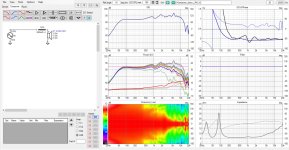
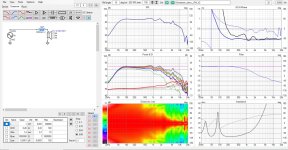
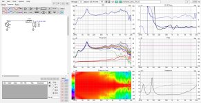
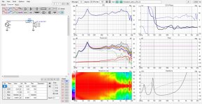
To start with, Dayton Audio SIG150-4 was used. An equivalent of 0.1*Zeq[SIG150] was used as a feedback discriminator, to get a voltage amplifier (LM3886, simplicity’s sake) with a gain in the range between 20 and 30dB. Of course, the feedback network cannot be universal. For SIG150-4:A reasonable amount of RF care was taken. The amplifier is stable. Measurements were taken by an 12dBA AudioTechnika 4040(Or 2020?) cardiod condenser microphone calibrated by ECM8000 calibrated by AZ8930, at 0.5m from the cone, while being adjusted to 1m loudness (60..85 dB SPL), in a moderately damped living room (RT60 ~= 250ms for f>200Hz). In the signal processing, frequency resolution was traded off to benefit precision and dynamic range (i.e. the curves have been denoised). Dotted lines correspond to the resulting noise floor for the given harmonic and excitation levels. The curves are positioned on the originating frequency, i.e. they correspond to the frequency that produces the harmonic, rather than where it appears, and are properly normalized for the cone frequency response (FR).
Results
Voltage Drive
Current Drive
Discussion
For LM3886, the depth of feedback is higher due to GBP=200kHz (46 dB on 1kHz). Most decent DIY Class A/B amplifiers have GBP over 1MHz. The depth of feedback can be improved by using second-degree astatizm and/or nested feedback. It is not entirely clear how to implement the current drive with non-self-oscillating Class D amplifiers efficiently.Note that an open-air inductor serves as an antenna and gets lots of interference, even after turning most of the switching PSUs in the vicinity off. In a real product, the inductor must be shielded.
If seen as necessary, the f<2Fs distortions can be dealt with by motion feedback. However, here the focus of the efforts is on the midrange drivers. Here, you do not need to worry about Fs lump.
90 dB @ 1m is as loud as SIG150 (sensitivity 91.1 dB @ 2.83V / 1m) can get without producing obnoxious distortions, both voltage and current drive. Sig150 is not capable of producing clean sound for f < 2*Fs, and multiple saturated resonances appear all the way through the passband, which is fairly typical for non-professional drivers.
The current sensing network is too sensitive to power and temperature variations. Thicker wire shall be used for the inductor and all resistors must be high-power rated. Satisfying the destruction limit is not sufficient distortion-wise.
It is not clear how far you can get with the current drive because you are limited by the cone distortions.
Conclusion
More experiments with different drivers, both Fe and Nd, both chirp and music to follow. The effect on Barkhausen noise (non-repeatable-in-details discretization of non-linear de/re-magnetization distortions) is most interesting for magnets that are never fully saturated because of the back current of the magnetizer and some domains are easier to flip than others.The drivers are implicitly optimized for voltage drive. The current-drive-optimized drivers may turn out to be quite different. It’s a terra incognita, for you to discover.
Waiting for the missing components to be shipped and delivered…
Copyright © Michael Zrull, 2024/09/19. All rights reserved. Released under GPL 3.0. I won't patent it nor restrict DIY by any means.
Could you elaborate on the difference between the 1st and 2nd graph of each group? Are graphs 2 and 4 normalised?
It also gives food for thought that AlNiCo magnets don't have that sharp transition between different material properties, so they would seem less prone to "grit" from magnetic snap-back effects. It motivates me to do something with electromagnets.
I'm curious about what happens at the glue line, where a typical ferrite ring connects to the iron ring. The iron seems like a "buffer zone" where the domains flex, but if the ferrite also flexes, it seems like there could be a technical case for aging and "burn in", as the magnet develops a second air-gap. Consider also that there is a gap there because of the glue thickness.The effect on Barkhausen noise (non-repeatable-in-details discretization of non-linear de/re-magnetization distortions) is most interesting for magnets that are never fully saturated because of the back current of the magnetizer and some domains are easier to flip than others.
It also gives food for thought that AlNiCo magnets don't have that sharp transition between different material properties, so they would seem less prone to "grit" from magnetic snap-back effects. It motivates me to do something with electromagnets.
D
Deleted member 375592
The first graph is the 2nd harmonics for the sine sweeps varying in level from 60 to 85 dB SPL, the second - of the 3rd harmonics.
I fully agree with your point about electromagnets.
I fully agree with your point about electromagnets.
The current drive version appears to have 5dB more output around 100Hz, and 5dB less NFB, which could partly account for the difference in harmonics. I wonder what they did to optimise the driver to make it look like it 'prefers' voltage drive?
For a while I grappled with an upside-down notch / "band boost" filter in the feedback circuit, and compared that against an active notch filter with pure current drive. But that didn't lead anywhere good with noise and distortion of the amplifier simulations. So for now I'm proceeding with mixed-mode feedback to try and get the best of both worlds.
For a while I grappled with an upside-down notch / "band boost" filter in the feedback circuit, and compared that against an active notch filter with pure current drive. But that didn't lead anywhere good with noise and distortion of the amplifier simulations. So for now I'm proceeding with mixed-mode feedback to try and get the best of both worlds.
D
Deleted member 375592
100Hz is about the Fs, so you have an increase in Q and therefore a bump in FR. The box is closed and well-damped by acoustic foam stuffed inside, so this 5dB increase is reasonable. The increase in harmonics is not explainable by any trivial theory, afaik, especially for the 3rd harmonics.
They (driver vendors) do not measure their products in any other configuration than voltage drive, do not test them, and most customers cannot experience anything else... so that's implicit optimization. Mostly intuitively, they make tradeoffs on the construction of the shorting (aka Faradey aka demodulation) ring which is of doubtful sense for the current drive. Explicitly, they use Klippel and COMSOL - again, in voltage drive. They surely know that the force is proportional to the current (not the voltage) but...
I do not understand what you meant by "active notch" and "pure current drive". Could you explain it?
Are you sure that you don't have a drawing error in the amplifier schematic ? To me this looks more like an oscillator than an amp !
Regards
Charles
Regards
Charles
D
Deleted member 375592
Yes, I am sure ... partially because it works as an amplifier. The driver has impedance ~10x of the sensing network.
And you don't think that both inputs are mixed-up in the diagram ?
Regards
Charles
Regards
Charles
Voltage drive is just a far much more robust and practical approach.100Hz is about the Fs, so you have an increase in Q and therefore a bump in FR. The box is closed and well-damped by acoustic foam stuffed inside, so this 5dB increase is reasonable. The increase in harmonics is not explainable by any trivial theory, afaik, especially for the 3rd harmonics.
They (driver vendors) do not measure their products in any other configuration than voltage drive, do not test them, and most customers cannot experience anything else... so that's implicit optimization. Mostly intuitively, they make tradeoffs on the construction of the shorting (aka Faradey aka demodulation) ring which is of doubtful sense for the current drive. Explicitly, they use Klippel and COMSOL - again, in voltage drive. They surely know that the force is proportional to the current (not the voltage) but...
I do not understand what you meant by "active notch" and "pure current drive". Could you explain it?
Especially seen from a consumer perspective.
Current drive could work, but it's going to be a case by case approach, even for drivers that would be optimized for such a thing.
Proper demodulation is an absolute must in current drive, because we want the inductance as stable as possible.
Because any difference in impedance will result in actual change in the frequency response.
Something that is inherently part of anything that is current driven.
Which also leads to potential thermal runaway problems when the Re rises with heat.
With voltage drive this would have a compression effect instead.
Because current drive is so super sensitive to any chance in impedance, it's automatically useless around the Fs of a driver, up to roughly 2-3*Fs.
Because the impedance around Fs WILL change as function of the cone excursion.
The only use case I can come up with. Are mid-range drivers that have a dead flat impedance, are crossed well above their Fs peak (incl cabinet) with active filtering, have a high sensitivity (= less heat) and a very minimum amount of cone excursion.
Or something like AMT's which have a flat impedance to begin with.
In voltage drive most of these issues just translate in (a bit of) distortion.
I have used an LEM LA25-NP current transducer to provide current feedback. This was a better approach in that there was lower power loss due to the lack of a series current-sensing resistor.
I found that the speaker system Q gets very high indeed with current feedback, but I will be using accelerometer feedback to control the system.
I found that the speaker system Q gets very high indeed with current feedback, but I will be using accelerometer feedback to control the system.
That is just fighting against evil for the sake of it.I found that the speaker system Q gets very high indeed with current feedback, but I will be using accelerometer feedback to control the system.
The benefits of current drive are at mid-range frequencies.
Low end is mostly dominated by BL(x) and Kms(x).
So voltage drive with an accelerometer will give you better results.
In fact, current drive won't do much at all in sense of distortion.
For the same reason that an accelerometer won't do much at midrange frequencies.
Klippel has some very good reads on this.
I once proposed the use of a simulated series output inductor instead of pure current drive for which I have posted a circuit somewhere here. This wold leave damping around fs approximatley the same but behave like current drive at higher frequencies. The resulting change in frequency response would of course have to be corrected but that isn't rocket science. The advantage of such a contraption would be a reduction of IMD caused by Le(x).
Regards
Charles
Regards
Charles
Not fully true because current drive eliminates the lowpass pole given by Le and makes the feedback loop easier to stabilise.So voltage drive with an accelerometer will give you better results.
Regards
Charles
Hi,Because current drive is so super sensitive to any chance in impedance, it's automatically useless around the Fs of a driver, up to roughly 2-3*Fs.
Because the impedance around Fs WILL change as function of the cone excursion.
You've got these mixed for some reason.
- In current drive the current is kept stable no matter the load impedance, so voltage varies with impedance.
- In voltage drive the voltage is kept stable no matter the load impedance, so current varies with impedance.
Impedance is literally relationship of voltage and current, if one is stable the other must vary with impedance. Current makes the force in the motor and determines the acoustic output, so if acoustic output varies with impedance it means current must vary, which means voltage is stable, which is voltage drive.
Last edited:
No I have notHi, You've got these mixed for some reason. Current makes force in the motor and determines the acoustic output.
Check your literature, or just do some very simple simulations.
I have done mine, so I am not gonna do that again.
Or are you now all of a sudden going to claim that SPL changes with voltage drive?
That is basically just a feed-forward solution.I once proposed the use of a simulated series output inductor instead of pure current drive for which I have posted a circuit somewhere here.
Could work, is not exact, and almost a solution that is looking for a problem.
I think you mix this stuff for this reason:
Speaker frequency response is ~flat because it was made for voltage drive! If you now use current drive it looks as if current drive fault the frequency response is wonky, but it's only due to the driver was optimized for voltage drive. Impedance varies with frequency, and impedance varies with SPL. So there is possibility to mix these up.
If there is a driver that has flat frequency response with current drive, driven with current drive, it would stay flat no matter the excursion because current is kept stable as per the current drive, no matter how the impedance varies with excursion.
If there is a driver that has flat frequency response with voltage drive, driven with voltage drive, it output would vary with excursion because the current varies with impedance, and impedance changes with excursion!
You could use either driver with either amp, the current drive would keep the acoustic frequency response stable, what ever that is. With voltage drive the response would vary as impedance varies with excursion current would vary!
*stability is relative, although current is stable magnetic field changes with excursion so also current drive would have some variation in output I think.
Last edited:
It sounds you're not that familiair with the concepts, so I would highly recommend doing some simulations first and see for yourself.I think you mix this stuff for this reason:
I have done the experiments as I mentioned earlier, which is also back-upped by other articles and papers.
Like one from Audioxpress, that clearly explains all the issues with current drive.
Coming to the same conclusion as I mentioned above.
I am not going over that whole repeat again, I am sorry.
I'm quite familiar with these stuff and see the logic break with many posts, like in yours today, that's why I commented. You can have it as you like, but if it prevents other people understanding the stuff I want to everyone have a chance to figure out themselves. This is not that critical stuff so everyone can understanding as they like, as long as everyone is able to make fine sounding systems which both drives certainly can, so pardon me picking this up. It's just that your expertise and experience and confident text output makes it read like a truth, while this time it is not so I'll stand up. There is nothing wrong being wrong, so that's also why I have courage to do this. Everyone here to learn, at least I'm and want to share what I've learned in return.
Here, voltage drive, response changes when impedance changes. Simply demonstrated swapping inductor in series with a driver:


Here current drive, response stays the same no matter the different load impedance, because output is determined by current which stays the same no matter the impedance.


Here, voltage drive, response changes when impedance changes. Simply demonstrated swapping inductor in series with a driver:


Here current drive, response stays the same no matter the different load impedance, because output is determined by current which stays the same no matter the impedance.


Last edited:
In that case, can you please show some results from your favorite Spice program?I'm quite familiar with these stuff and see the logic break with many posts,
VituixCAD can't do this, because it can't simulate a true current drive circuit.
A high impedance resistor in series does NOT do the same thing!
There is not break in logic in here at all, it's how physics work I am sorry.
Because I am quoting from actual resources and experiments.It's just that your expertise and experience and confident text output makes it read like a truth,
Otherwise I would simply write it as "in my opinion" or "I think that"
In this case it's not a matter of opinion.
And I am really sorry about my grumpy response, but there is absolutely a TON of good information about this, plus it's not hard to actually simulate a real current drive circuit in LTSpice, use the actual loudspeaker equivalent circuit and simulate all the parameter changes accordingly.
That is just not the same as adding an external resistor and inductor.
But I can already feel like I am spending another great deal of time repeating things over again because people are so convinced about something.
And I know you're are a great guy that can handle a mature discussion (even with disagreement), so there is nothing personal here. But sometimes it's getting a little stale and old. again nofi.
edit: I think I have even posted some examples, graphs and results with all the runaway and Fs issues etc
Which was basically showing the practical results from what is written in the literature.
Last edited:
- Home
- Loudspeakers
- Multi-Way
- Experiments with the current drive