Suppliers like Mouser give filter options like composite or iron powder (searching under power inductors or common mode chokes). The exact formulations probably vary by manufacturer though.
Driver designers would love to use segmented/laminated structures that eliminate/minimize eddy current paths, it's just almost impossible to build them with reasonable effort, as of yet.
Purifi is working on that problem, AFAIK.
Were the eddy currents ever a problem though? In voltage drive they just help to flatten the response, complimenting the cone's acoustic gain. They behave the same as a weak shorting ring but to much lower frequencies due to the skin depth in steel. Having no eddy currents would actually make the problem worse because the eddy currents mitigate flux modulation and hysteresis. A laminated pole piece would give a hard inductance, so your cone would also have to have a steeply rising treble response in voltage drive. But then I suppose for a woofer this would just be a convenient HF rolloff.
The main issue I'm aware of with eddy currents is that while there is a current in the voicecoil, they produce a nonlinear drag which increases H3 quickly with level. I haven't seen many signs of this in the usual drivers though so I think if it is an issue it must be at very high powers.

I'll take any FR deviation before hysteresis distorsion. There is EQ to fix FR, but no remedy for hyst.
//
//
Shorting rings around a laminated pole piece could reduce hysteresis in the mids, but at frequencies lower than the shorting rings can operate, you will get more hysteresis because only a solid pole piece is thick enough and lossy enough to have a shorting effect at those frequencies. I could be wrong, but I don't think it's that simple.
The resistance of copper is 1000x less than iron, so I think the frequency where it loses effectiveness will be subsonic. So I am probably wrong about this. The ultimate inductance due to the pole piece is hard to measure.
I don't know how I got that 1000x figure, but it's more like 10-40x depending on what is being measured. So not that anybody cares anymore, but I question whether a laminated motor makes sense, it seems like it would come with it's own problems unless it was also a different alloy or used in a very different way than I'm imagining.
Meanwhile I started measuring current distortion with a voltage driven speaker driver.
In that case Visaton W170S8 in about 10l enclosure.
The plot shows FFT with 1V/20Hz applied to the voice coil.
We see considerable harmonic distortion -
what I do not see at all is any indication of Barkhausen noise.
I assume that the harmonics are due to motor imperfections and spider non-linearity as well.
tbc
Attachments

Last edited:
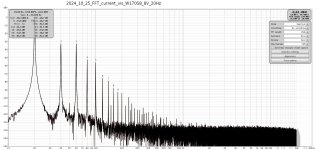
3/5/7/9 look like classic hysteresis at 1V. The rise in the noise floor at 8V could be it. You could try it with a load resistor instead, to make subtle differences more obvious, for instance widening of the bases of the peaks.
Meanwhile I started measuring current distortion with a voltage driven speaker driver.
In that case Visaton W170S8 in about 10l enclosure.
The plot shows FFT with 1V/20Hz applied to the voice coil.
We see considerable harmonic distortion -
what I do not see at all is any indication of Barkhausen noise.
I assume that the harmonics are due to motor imperfections and spider non-linearity as well.
tbc
So What does "iron noise / distortion" look like?
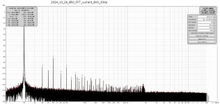
In general, noise cannot be properly assessed on a dBV scale, and the apparent 'floor' also depends on the sample size. Noise also cannot be defined at any single frequency but always needs a given bandwith and is better described on a V²/Hz or V/sqrt(Hz) scale. This makes quantifying tones and noise on the same plot difficult.
Agreed. For that reason I did measurements with max FFT len (4M) with speaker driver and a dummy resistor for comparison.
There is a slight difference in noise floor - telling me the effect of Barkhausen noise is neglible in my setup.
More measurements not availabe, because my soundcard has got a hardware problem.
There is a slight difference in noise floor - telling me the effect of Barkhausen noise is neglible in my setup.
More measurements not availabe, because my soundcard has got a hardware problem.
Attachments

In general, noise cannot be properly assessed on a dBV scale, and the apparent 'floor' also depends on the sample size. Noise also cannot be defined at any single frequency but always needs a given bandwith and is better described on a V²/Hz or V/sqrt(Hz) scale. This makes quantifying tones and noise on the same plot difficult.
Not so fast, that may be sneaking out the back door.
Setting aside things like hum and buzz, noise is random and will not stand out in an FFT as in the frequency domain.
If "iron noise / distortion" is as is reported not so random, perhaps will show up in an FFT plot.
If "iron noise / distortion" falls more in the time domain it will show up on an Oscilloscope output.
The reports that we hear is that Barkhausen noise and other "iron noise / distortion" is "on this side of audible".
I would expect a rising noise floor
I would expect that bucks bunny is correct.
The FFT's that I have been shown of reported "iron noise / distortion" caused by laminated core crossover inductors looks much like bucks bunny FFT plots with 6 to 10 dB greater amplitude in the up to 1kHz frequency range.
Thanks DT
Last edited:
If you scroll through the whole page there are many charts that explain very well visually what is happening:
https://e-magnetica.pl/doku.php/barkhausen_noise

Because the noise is in bursts, frequencies that are not a multiple of the burst frequency tend to cancel out compared to non-modulated noise, hence strong base widening at 2KHz and favoring 4KHz. During a long steady-state measurement, the peaks will mainly average out and will show up at a low level on the measurement when in fact they could be highly audible compared to how they appear on the FFT. Sine wave measurements are pretty much the worst case for seeing this because we normally increase the FFT points specifically to average out noise. This is one of the main reasons for FSAF measurement as I understand.
https://e-magnetica.pl/doku.php/barkhausen_noise
Because the noise is in bursts, frequencies that are not a multiple of the burst frequency tend to cancel out compared to non-modulated noise, hence strong base widening at 2KHz and favoring 4KHz. During a long steady-state measurement, the peaks will mainly average out and will show up at a low level on the measurement when in fact they could be highly audible compared to how they appear on the FFT. Sine wave measurements are pretty much the worst case for seeing this because we normally increase the FFT points specifically to average out noise. This is one of the main reasons for FSAF measurement as I understand.
If you scroll through the whole page there are many charts that explain very well visually what is happening:
https://e-magnetica.pl/doku.php/barkhausen_noise
Because the noise is in bursts, frequencies that are not a multiple of the burst frequency tend to cancel out compared to non-modulated noise, hence strong base widening at 2KHz and favoring 4KHz. During a long steady-state measurement, the peaks will mainly average out and will show up at a low level on the measurement when in fact they could be highly audible compared to how they appear on the FFT. Sine wave measurements are pretty much the worst case for seeing this because we normally increase the FFT points specifically to average out noise. This is one of the main reasons for FSAF measurement as I understand.
Thanks for the post.
So on a time domain scale we can see bursts of noise that occur at twice the test frequency. There is a random noise quality and a frequency quality to the "iron noise / distortion".
I suspect that if there is a Two-Tone test signal applied that there is a IMD Amplitude Modulation version of Barkhausen noise / distortion that makes an appearance.
Thanks DT
I tried to interest people in "How to design a speaker optimised for Current Drive"; in another forum IIRC. No one seemed interested .. certainly no true speaker gurus who would be required for such a project.What would a better motor consist of? Electrostatic?
//
But TNT, you win the prize for the correct answer. 😊
The constant charge push pull electrostatic as per Baxandall & Walker is the most practical current drive optimised transducer.
In Jurassic times, I nutted out such a design which has some rather nice properties eg high efficiency & sensitivity and discussed this this Peter Walker. Alas, it needed a couple of Unobtainium bits which I found are still Unobtainium this Millenium.
No present Electrostatic comes near mythical beast.
PS The current drive optimised speaker I proposed wasn't this beast but a moving coil based one. I would be very different from our usual MC speakers.
Last edited:
Really interested in this Barkhausen s**t.
Spent most of my previous life dreaming up and correlating supa dupa speaker measurements and DBLTs with some success.
Loadsa time simulating various distortions to find audibility levels for each.
Is Mike's FSAF stuff, now embedded in REW, the only repeatable method to get a hook on this? Bill Waslo & Hornli suggest you can hear it clearly on LF sine.
Do we need large signal levels or does it happen at low levels like xover or quantization distortion?
Last edited:
Based on the audio clip in that link, avalanching occurs mainly at the saturation knee, which does not bode well for the saturated pole piece theory. Other than that, it seems to have a monotonic relationship with level, IE at lower levels you will have less Barkhausen noise. It seems to depend on the level reached at the last peak, which effectively sets a number of domains up for flipping or avalanching if it is closer to saturation.
What I learned from MIDI in my teens was that when you record a sound and play that sound over and over again on a keyboard, any imperfections in the recording become blaringly obvious. So I think making a recording of a sine wave and looping that sound would bring out Barkhausen noise pretty well if it is audible. It could be compared to a clip of just the background noise looping.
If you remove the sine wave then the distortion itself may be audible, but it may sound completely different than how it is perceived in combination with music.
- Home
- Loudspeakers
- Multi-Way
- Experiments with the current drive