Yes I noticed those (along with the AK4396 kit which I've just ordered). But this thread is about the Gigaworks 24/192 DAC - and it looks like it's being phased out - would be a shame 😕
The AK4396 can work with transformer output. A sensitive chip to heat, but that may be avoided by taking the signal somewhere that's a safe distance from the chip itself.
Would this be correct?
Would this be correct?
Are the PCM2706 any good compared to DIR 9001 e.x.?Yes I noticed those (along with the AK4396 kit which I've just ordered)
Are the PCM2706 any good compared to DIR 9001 e.x.?
I don't have a clue unfortunately...
So does anybody know for sure if this Gigaworks 24/192 DAC is being/has been phased out? Would be a shame to see it go after the extreme length of this thread and all the DIY tweaking.
Still all good things come to an end I guess 😱
The AK4396 can work with transformer output. A sensitive chip to heat, but that may be avoided by taking the signal somewhere that's a safe distance from the chip itself.
Would this be correct?
I don't know. There's a separate thread for the AK4396 DAC...

That's a big pic 😛
Yeah, that looks the business, is there a thread on that one? or is it in this one somewhere?
Ian.
Edit:must be the site or my browser, but that pic has a life of It's own...
Yeah, that looks the business, is there a thread on that one? or is it in this one somewhere?
Ian.
Edit:must be the site or my browser, but that pic has a life of It's own...
Last edited:
Yeah, that looks the business, is there a thread on that one? or is it in this one somewhere?
No thread on that, and also not in this one yet. I'll post more tonight.
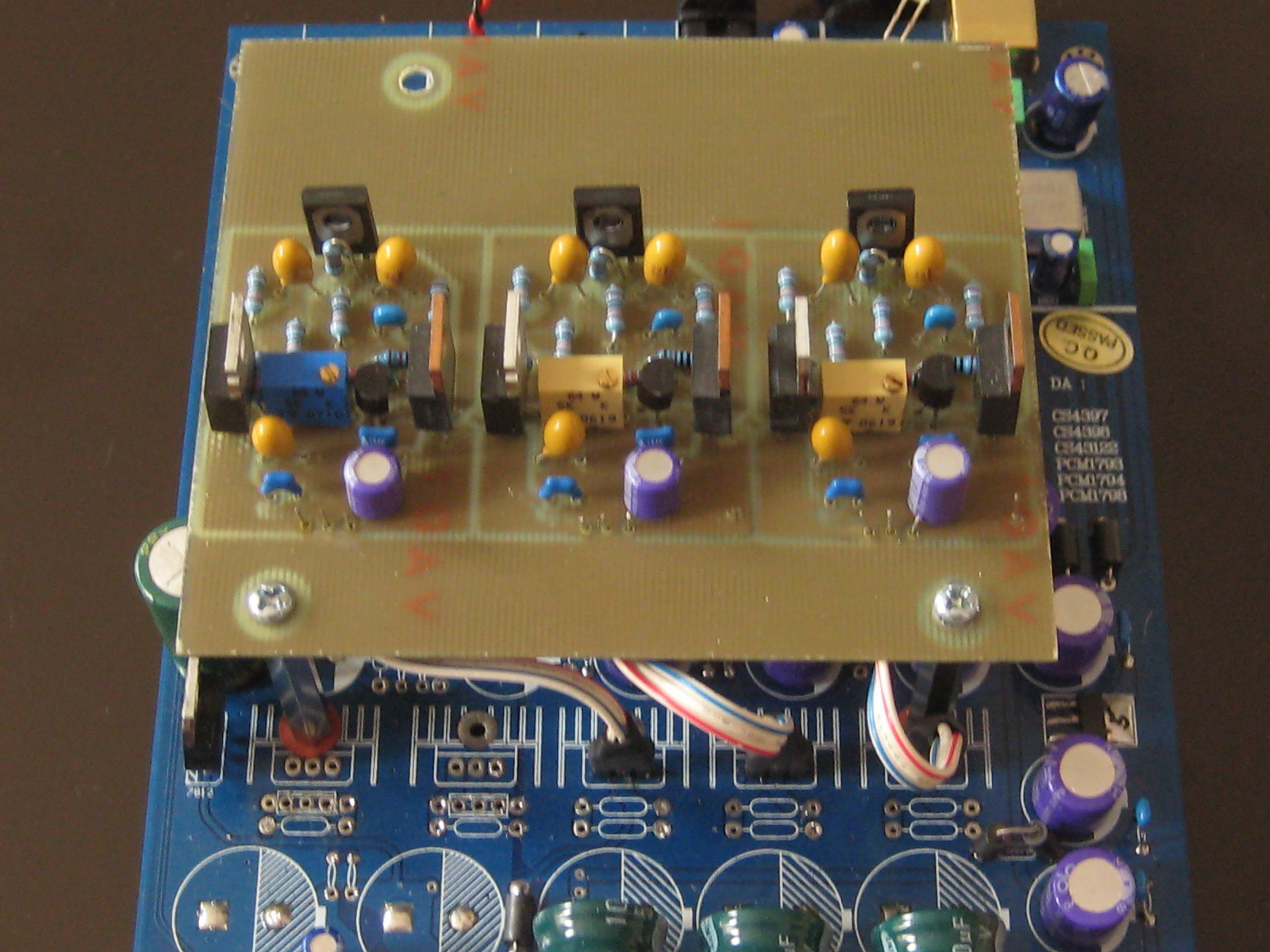
Here are the PDF files for the preregulator board. It is made to fit to the DAC board. I've ripped off the whole PSU stuff from the DAC board and feed the prereg's outputs to the DC sides of the diodes on the DAC board.
This is the schematic for the prereg, borrowed here: Using 3-pin regulators off-piste: part 4 )
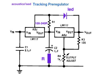
The C-R-C-R-C filters and diode bridges need no explanation, I think.
Edit: I've just noticed that the LEDs are drawn reversed in the component layer PDF!
This is the schematic for the prereg, borrowed here: Using 3-pin regulators off-piste: part 4 )
The C-R-C-R-C filters and diode bridges need no explanation, I think.
Edit: I've just noticed that the LEDs are drawn reversed in the component layer PDF!
Attachments
Last edited:

My pleasure. The boards are selfmade, so no sale nowhere. When I start the next PCB production run in my kitchen, I could make one for you and send it to you. But with cutting and drilling you were on your own. (I'm hating it ...)
Great work G'loops!
I think theat Teddy Pardo sells a complete regulator board the upgraded "Super Teddy Reg". TeddyPardo
This is probably a stupid question but what is the value for R in the acoustica TPR design?
G'loops did you detect a tangible sonic benefit from using the TPR and Teddy?
Cheers,
George.
I think theat Teddy Pardo sells a complete regulator board the upgraded "Super Teddy Reg". TeddyPardo
This is probably a stupid question but what is the value for R in the acoustica TPR design?
G'loops did you detect a tangible sonic benefit from using the TPR and Teddy?
Cheers,
George.
I think theat Teddy Pardo sells a complete regulator board the upgraded "Super Teddy Reg".
Paying 142 whiplashes for three regulators ... Never!
The R value is well hidden 😉 in the text on the Acoustica page: "As to typical values ror C2 = Polyester 0.1uF in series with R5= 10ohms, or C2=1uF in series with R5=2R7 - 3R3; or a cheap 10uF electrolytic cap all work well here."
I've not tested the Teddyregs in curcuit yet. The preregs alone gave a noticeable improvement, no surprise. The original onboard LM317 implementation is in the most basic manner without any kind of filtering.
Many thanks! I will give the acoustica article a closer read.......I've been keeping an eye on the updates for a while now.
I had to cut some tracks on the main PCB to seperate the supply rails have you done the same?
Also I've been playing with decoupling using 0.01uf X7R on 100nF eloctrolytics soldered directly to the daughter boards of the cs4398 and cs8416; Vref VA etc, I have also removed the FB and regulator on the 8421 board and decoupled the supply to the clock with 0.01uf X7R. All of this together resulted in a substantial improvement in sound. I found that until all of it was done the sound was not balanced at all??
To be honest this is a lot of work to get a decent "audiophile" fidelity! This is beyound upgrades, the board is slowly being redisgned.
Very interesting thread. I plan to buy this kit, but there's 2 version : red PCB and green/blue (unclear) PCB...which one is the new & most updated ? I believe both version support upsampling module, am I right ?
I had to cut some tracks on the main PCB to seperate the supply rails have you done the same?
I've only cut one track on the CS4398 smurfboard. Which tracks did you cut? A photo would the nice ...
... the board is slowly being redisgned.
That's what I'm working on. More on that within the next days.
- Home
- Source & Line
- Digital Line Level
- Experience with this DIY DAC ?