Try to solder wires to the jumper pins,and then to the switches.I have done this to the new version and I hadn''t problem.
Hello there,
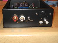
I own the old version of the Gigaworks DAC:
New 24/192 DAC DA CONVERTER CS8416+CS8421+CS4398 USB | eBay
You can see it in the third picture, some people here have built the same version or the very similar version that was sold before.
I wonder if anyone made it possible to switch the input from the outside of the enclosure? In this version the inputs can only be changed by using the jumpers.
Any1 got an idea how to do that?
I use dual-ganged 3 position toggle switch with the following wiring referenced to the board connections (which are labelled incorrectly):
Switches
USB SA=1
Opt SB=1
Coax Both SA, SB open
Mine is the latest board though and may be different from the earlier version.
I use dual-ganged 3 position toggle switch with the following wiring referenced to the board connections (which are labelled incorrectly):
Switches
USB SA=1
Opt SB=1
Coax Both SA, SB open
Mine is the latest board though and may be different from the earlier version.
The Lars Audio version of this DAC which was sold to me in a case, also uses the same three position switch concept. I see that they have now gone with a rotary switch. I've never hooked this DAC up to USB, but the coax and optical work as expected.
Sheldon
The only other switch I see that is needed, is to switch from upsampling to non-upsampling. 192k files do not work with the upsampling module installed.
Has anyone done this?
Has anyone done this?
I know the USB input can't handle 192, but I dont have any high rez files any way. I can't see why it wouldn't work with coax with upsampling though.
Best, Bill
Best, Bill
The only other switch I see that is needed, is to switch from upsampling to non-upsampling. 192k files do not work with the upsampling module installed.
Has anyone done this?
The max sample rate in upsampling mode is 176.4k, because if you already have 192k wav file, you don't need to upsampling.
In my opinion, only if you are using unproper digital source, such as DVD player, otherwise, the upsampling module is not necessary.
Green coupling caps
Hi everyone,
Just wanna know did anybody upgrade the green 'ero' coupling caps around the dac and the receiver chip to something better.
Would like to hear any experience at this part...
Hi everyone,
Just wanna know did anybody upgrade the green 'ero' coupling caps around the dac and the receiver chip to something better.
Would like to hear any experience at this part...
ASRC Bypass Mode
The ASRC chip CS8421 does have a bypass mode on pin 6. On the Up-sample board there's a 47k pulldown resistor, you could add a switch to take pin 6 high for pass-through, but then you need to change Fs on the DAC IC too.
Earlier, I posted the schematic for this DAC (Lars Audio) Posting #3728
The ASRC chip CS8421 does have a bypass mode on pin 6. On the Up-sample board there's a 47k pulldown resistor, you could add a switch to take pin 6 high for pass-through, but then you need to change Fs on the DAC IC too.
Earlier, I posted the schematic for this DAC (Lars Audio) Posting #3728
Transformer output again

I tried a pair of Lundahl LL1517s (Primaries and secodaries in series, displayed simplified) as shown above and it sounds quite good to me that way. Is there something to do better?
Then I stumbled across a schematic as shown below. What I don't get: What should one bias the primaries with DC? Is there any benefit?

And what grounding is that on the output?
I tried a pair of Lundahl LL1517s (Primaries and secodaries in series, displayed simplified) as shown above and it sounds quite good to me that way. Is there something to do better?
Then I stumbled across a schematic as shown below. What I don't get: What should one bias the primaries with DC? Is there any benefit?
And what grounding is that on the output?
Stepping into the transformer flames again... Cheapo audio transformers have the primary and secondary "scramble wound" on top of each other, so you get huge (unbalanced) capacitance between them. I find this with the Edcor PC series 😡 for example.
At high frequencies, the DAC IC no longer sees a symmetrical load.
Somewhat of a fix is to try keep the DAC load balanced, by adding a cap on the center-tap to keep it an AC ground (the huge 22uF cap). Aout sits at VA/2 or 2.5VDC, at 10k that's 0.25mA which doesn't do much to the DAC IC's output stage bias. I think the 10k resistor is a bleeder for the cap.
A second effect of the unbalanced inter-winding capacitance is stray coupling hum and noise between primary and secondary, and grounding the secondary helps.
The Lundhal LL1517 is decent with isolated windings, electrostatic shielding so you wouldn't have to deal with any of these problems.
jfet out stage
there Is an old thread about Sony output stage mod http://www.diyaudio.com/forums/digi...age-sony-cd-players.html?highlight=stage+sony
Justcallmedad suggest this http://web.archive.org/web/20070219232819/http://perez.r.free.fr/XB_out_fet_dc_0v.JPG as output stage for Vout chips
I like to know what are your thoughts and specially Bill Fuss about this schematic to use with CS4398/97 Vout chips
Stepping into the transformer flames again... Cheapo audio transformers have the primary and secondary "scramble wound" on top of each other, so you get huge (unbalanced) capacitance between them. I find this with the Edcor PC series 😡 for example.
At high frequencies, the DAC IC no longer sees a symmetrical load.
Somewhat of a fix is to try keep the DAC load balanced, by adding a cap on the center-tap to keep it an AC ground (the huge 22uF cap). Aout sits at VA/2 or 2.5VDC, at 10k that's 0.25mA which doesn't do much to the DAC IC's output stage bias. I think the 10k resistor is a bleeder for the cap.
A second effect of the unbalanced inter-winding capacitance is stray coupling hum and noise between primary and secondary, and grounding the secondary helps.
The Lundhal LL1517 is decent with isolated windings, electrostatic shielding so you wouldn't have to deal with any of these problems.
Mind for me to ask extra question.
Is this practice applicable to all output traffo as a dac output...???
there Is an old thread about Sony output stage mod http://www.diyaudio.com/forums/digi...age-sony-cd-players.html?highlight=stage+sony
Justcallmedad suggest this http://web.archive.org/web/20070219232819/http://perez.r.free.fr/XB_out_fet_dc_0v.JPG as output stage for Vout chips
I like to know what are your thoughts and specially Bill Fuss about this schematic to use with CS4398/97 Vout chips
At first glance it looks like a simple, 0 gain source follower with a LTP servo tacked on to the output, feeding back to the CS under the signal jfet.
If you have the parts, build it and try it out. If you have to buy the j74s that's going to cost you some bucks. You could try J103s instead of J74s, they are still cheap.
Best, Bill
thx Bill I will try It - It will be far less expensive than transformers
I got some questions regarding this schematic
1) R101 and R110 cancel out DC offset ? For CS4398/7 which Is 3 Vdc what value of trimmer Is recomended
2) what Idss sj74/103 are needed
3) I will use only one of R117, R118 ?
4) can C101, C102 be electrolytic type
I got some questions regarding this schematic
1) R101 and R110 cancel out DC offset ? For CS4398/7 which Is 3 Vdc what value of trimmer Is recomended
2) what Idss sj74/103 are needed
3) I will use only one of R117, R118 ?
4) can C101, C102 be electrolytic type
It would be best to contact someone that has used this circuit for better answers.
4. These caps shunt the signal to ground, they are not in the signal path, use whatever you have.
3. I have no idea what they are doing, probably dual dac chips.
2. Anything over around 6ma, they are not in the signal path either.
1. They are load resistors, the J74 differential pair controls the offset by feeding it back to the gates of the bottom K170s.
The trimmers are 10 ohms, and the J74s need to be matched pairs.
The only parts directly in the signal path are the top 2 jfets, and the input and load resistors. The rest is current sources and servos.
You can also replace the J511s with a K246 or K170 set up for 5ma. Look up the Borbely jfet articles, I don't have a link but they are out there.
You need a really good PS for this, are you sure it's going to be cheaper than trafos? I bought a pair of Jensen JT-11DMs off of Ebay for $56.
Best, Bill
That's a lot of parts, I would be hard pressed to build that for less than $56. But I'm pretty sure I could do it for less than the $250 that my Lundahl's cost me.. Getting jfets is hard these days.
However the question remains, does it sound any better than a good op-amp (op627 or LM4562)? Will the effort be worth it? Only you can know for sure.
Sheldon
However the question remains, does it sound any better than a good op-amp (op627 or LM4562)? Will the effort be worth it? Only you can know for sure.
Sheldon
Since today I own the miniDSP and now I dont want to use the internal DAC.. but my Gigaworks DAC. So the problem ist that I need two Gigaworks DACs now IF I want to use two two way active speaker systems..
Is there another option than simply buying another Gigaworks DAC board? Problem is that I Would need 4 channels and at least two digital inputs... its really complicated to build a DIY active speaker system.
Is there another option than simply buying another Gigaworks DAC board? Problem is that I Would need 4 channels and at least two digital inputs... its really complicated to build a DIY active speaker system.
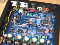
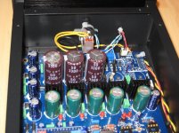
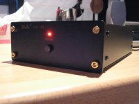
Almost finished !
Some pics of the almost finished DAC, inside a case left from another DIY DAC, the
LITE DAC-AH (http://cgi.ebay.ch/LITE-AUDIO-DAC-AH-96-24Bit-HI-END-Mini-DAC-/320669530848)
A 96/24 using 8 parrallel TDA1543, quite nice but not in the same league...
Anyway, I find this case nice looking, and just big enough to accomodate the board.
Quite a lot of work to make it fit, but in the end il looks more like a finished product
than some garage job.
And the vendor of the AH DAC also sell the naked case, around 25$.
I'm just waiting for the Sowther transformers to make it sing 😉
And I got a dumb question, as I put the board in (tightly secured with strong double sided tape), I didn't write the output order of the DAC, doh ! Can somebody confirm it's R+, R-, L-, L+ ? Thanks !
Attachments
- Home
- Source & Line
- Digital Line Level
- Experience with this DIY DAC ?