McGyver said:
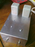
3 black cap cans are power supply for the tube (see the picture).
If you are going to use output transformers alone and omit tube buffer, you will not need this caps. Nor output caps (big blue boxes) either.
I'm going to be doing Transformer MOD with cathcode follower need 2 tubes for stereo, jesus! does that Mean I'll need 6 cans (powersupplys) and 4 output caps ??.
Sorry about this its my first MOD....Ever.
shuggi67 said:
I'm going to be doing Transformer MOD with cathcode follower need 2 tubes for stereo, jesus! does that Mean I'll need 6 cans (powersupplys) and 4 output caps ??.
Sorry about this its my first MOD....Ever.
Cathode follower... You need two triodes, it's one tube. You need one power supply PCB with 2 or 3 caps and 2 output caps.
Ciu said:The Tamuras are on a specific board, because those I bought were with very short wire, I had to install with much more precaution , and would not have to move twice.
Resistors and caps around Tamuras are installed to be removed anytime I want, until tests ended (successfully ?)
I use Tamura with Buffalo ESS9008 Dac (Twisted Pear Audio), and have a McIntosh Pre C24, not sure to need a cathode follower.(althought I agree with McGyver about tamura 's output impedance)
Before Tamuras, I made a Broskie Cathode follower, with differential input, using 6GM8 and 24v "B+": sounds very nice but need 2 more transfos !
I'm a "Keep It Simple" adept
R.C.
Can you clarify this for us. Unless I am mistaken, the Buffalo is a current out dac so you are using a tube circuit for the I/V conversion, then you are feeding that to the trafos. And you need two more trafos for what? Doesn't sound simple. What is Tamura's output impedance?
Best, Bill
The Buffalo DAC 9008 has two modes : current and voltage, you can connect it has you want
It has an output impedance of ~190 Ohms ( Twisted Pear Audio board configuration )
So I connected it as another voltage Dac, CS4398
Regarding Legarem's advice (Thanks !) about the loading ratio of 1/10, I connected the dac + 600R primary 600R -
a 1,5nf capacitor is across primary
Secondary is loaded with 600R only (must test RC network)
This is my first configuration , have to test other values as filters
Sound is natural, details and bass are there !
R.C.
Attachments
Thanks for clearing that up. I looked up the Buffalo and it has a big DC offset so you cant tie it right to trafos. Did you try coupling caps instead of the buffer.
Bill
Bill
In a voltage DAC, like CS4398, Buffalo, there is offset between + and Gnd, - and Gnd
There's no offset between +-, (already said by LeGarem I think )
I have NO buffer in my Dac
Buffalo + > R600 > Primary > R600 >Buffalo -
1.5nF // primary as LPF
Tamura Secondary : // R600 > McIntosh Pre
That's all ! Nothing more !
R.C.
There's no offset between +-, (already said by LeGarem I think )
I have NO buffer in my Dac
Buffalo + > R600 > Primary > R600 >Buffalo -
1.5nF // primary as LPF
Tamura Secondary : // R600 > McIntosh Pre
That's all ! Nothing more !
R.C.
Attachments
Now I see, you used the trafos to replace your previous output circuit. What I read on the twisted pear website led me to believe the Sabre had a large DC offset, I'll have to find the data sheet on it.
You don't need a load on an output transformer, just a filter.
Best, Bill
You don't need a load on an output transformer, just a filter.
Best, Bill
Hi Bill,
The voltage offset is 1.65V, from + or- to ground.
I tought of using transfo on my Buffalo too. No need for series resistances in the primary.
The sabre DAC is a current output dac. That is the prefered mode of operation: lower noise and reduced distortion. It can be used in voltage mode, with reduced performances, theoricaly.
The performances of this chip are so good that it may not show at all.
I discussed it with Russ White about it and he is convinced that transformer coupling will work very well, although the dac will operate in voltage mode now. (40 ohms at primary)
Personnaly I did not do it because the IVY is designed for current mode operation. The overall performances of this Buffalo is so good, I don't know what I could gain with a transformer.
Jean-Charles said:Hi Bill,
The voltage offset is 1.65V, from + or- to ground.
I tought of using transfo on my Buffalo too. No need for series resistances in the primary.
The sabre DAC is a current output dac. That is the prefered mode of operation: lower noise and reduced distortion. It can be used in voltage mode, with reduced performances, theoricaly.
The performances of this chip are so good that it may not show at all.
I discussed it with Russ White about it and he is convinced that transformer coupling will work very well, although the dac will operate in voltage mode now. (40 ohms at primary)
Personnaly I did not do it because the IVY is designed for current mode operation. The overall performances of this Buffalo is so good, I don't know what I could gain with a transformer.
And what about using an I/V with a resistor and adding a transformer to isolate te dac ?
Maybe the i/V conversion could be done simply by a transformer.
Voltage dacs use the devil (op amps at their output). If you can get rid of op amps, it is the best.
Jean-Charles, je voudrais bien discuter de ce dac par téléphone avec toi.
McGyver said:
3 black cap cans are power supply for the tube (see the picture).
If you are going to use output transformers alone and omit tube buffer, you will not need this caps. Nor output caps (big blue boxes) either.
I thought the blue things where transformers/power bricks ? i.e one for DAC and one for tube is that what a Output Capacitor is.
For the 3 anode caps is 100uF/450 v ok or am I best finding 200v caps.
And what ratings should I be using for the Output Cap.
Cheers
A little bit of French for Marc.
Je pars demain pour Baie St-Paul, de retour le 5 ou 6 juillet. On se donne rendez vous. Laisse moi tes coordonnées si tu veux que je rapelle.
Marc, transformers are essensially current devices. Adding series resistors acts as current limits and also reduces signal level. The I/V conversion is accomplished by the loading resistor in the secondary. This is not necessary with the Sabre; you can short the output and it won't damage the dac.
The IVY supplied by Twisted Pear presents a virtual short to the Sabre chip. This is the prefered mode of operation.
The Tamura transformer has a primary resistance of 40 ohms, not zero. Although this will work fine it will automaticaly change the operation from current mode to voltage mode.
I am always very carefull with absolute statements that say one thing is bad and the other is the only avenue, etc. I have seen too many.
I was planning, when I purchased the Buffalo, to design my own tube section as I did with my present dac based on the TDA1541A. For balanced operation this would require 4 tubes and all associated esoteric components, plus change to voltage mode.
Of course it would be very good as is my present set up, but hours of listening to the Buffalo, convinced me that the effort was not justified sonicaly nor money wise.
Did you tried to connect transformers, at the Buffalo output, without resistors as current limiters ?
With 190 Ohms as internal impedance with Buffalo, and 40 Ohms primary transfos as load, what would be the voltage at secondary ? 40/190 x primary voltage ... No ?
May be I'm wrong ?
R.C.
With 190 Ohms as internal impedance with Buffalo, and 40 Ohms primary transfos as load, what would be the voltage at secondary ? 40/190 x primary voltage ... No ?
May be I'm wrong ?
R.C.
I have a pair of NOS UTC A-20 transformers arriving soon. Can someone post a simple connection schematic for taking the signal from the DAC chip to the amp please? (I will be using a linestage pre).
MANY thanks and Good Luck too,
Brian
MANY thanks and Good Luck too,
Brian
brianco said:I have a pair of NOS UTC A-20 transformers arriving soon. Can someone post a simple connection schematic for taking the signal from the DAC chip to the amp please? (I will be using a linestage pre).
MANY thanks and Good Luck too,
Brian
Try the link on post 349, just omit anything to ground.
McGyver said:New DAC is born. Trannies are Monacor LTR110, ugly looking, but noble sounding. No difference I can hear in comparison to Sowters.
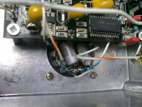
the two trannies look different, are the both Monacor LTR110's also what are the 2 smaller looking transformers beside the big blue cans ?.
shuggi67 said:
the two trannies look different, are the both Monacor LTR110's also what are the 2 smaller looking transformers beside the big blue cans ?.
The two trannies ARE different. Both are power supplies, one for DAC and one for tube. The 2 smaller looking transformers beside the big blue cans are LTR110.
some photos of how I integrated my DAC
some people are calling it 'noodle_dac++' since its almost like a followon to the noodle_dac (lampizator thing) 😉
I integrated some neat things, here, such as a super large LCD display, arduino processor, burr brown PGA vol control chip and my own 'VoluMaster' software to control it all. an ordinary sony dvd player IR remote controls it. there is also an x10 'firecracker' interface for wireless comms to turn powerline things on/off (think: slaved power amps).
some photos, now:
testing the bare board:
http://farm3.static.flickr.com/2421/3552277335_eabcaf565a_o.jpg
the dac box (left) next to my B22 amp (right):
http://farm4.static.flickr.com/3630/3639849537_698b1eb840_o.jpg
inside the black box with minimal hookup (test bed 1):
http://farm4.static.flickr.com/3578/3655856250_f4bafeeb81_o.jpg
http://farm4.static.flickr.com/3343/3655111527_9ed6b61f4e_o.jpg
this is what I have today (test bed2):
http://farm4.static.flickr.com/3338/3662956051_ccbd077719_o.jpg
http://farm4.static.flickr.com/3645/3662955491_d73cf40a52_o.jpg
the small green board is a PGA vol control board that the arduino talks to. the board is from 'ERROR401' (he posts to various forums, perhaps here as well).
the arduino also switches inputs from coax to opto via a single bit on the arduino's digital pin array.
there are MANY software features (I'll release my code when its mature. either BSD or GPL based, probably). the most interesting is that it uses ethernet/IP to talk to a remote linux 'mpd' sound daemon server over regular wired IP. there's an apache webserver on that linux box and when the user presses 'NEXT' on the sony IR remote, the black box receives it (arduino), formats a GET request for the remote webservers and sends it. this will pause or play or skip songs but it also sends queries every 3 secs to get the current song remain-time value, so that it can update the graphics live on the lcd.
soft ramp up/down on mute (and also on power on/off), user settable hi/low volume levels, named input/output device selection, software controlled lcd backlight, even a sleep timer to turn everything off once an hour has passed (I'm serious).
Here's my attempt with the smaller dac board.
I used an LM337 regulator to give me 5V - this powers the digital section of the board. The analog side isn't powered as I'm taking the output from the dac chip to a pair of UTC A-43 trannys. The transformers have the filter detailed in the Jensen pdf - the cap and resitor values are slightly different as I used 2.17nF and 1.04nF russian FT-3 caps rather than the 2.2nF and 1.2nF values Jensen recommend. I adjusted the resistor values to keep the filters close to the frequencies of the Jensen ones.
All electrolytics are replaced with tantalums. The PLL is replaced with the correct value components.
Attachments

- Home
- Source & Line
- Digital Line Level
- Experience with this DIY DAC ?