Is there any better pot to upgrade without cutting. Just remove stock and solder better part. I see some TKD pots on forum but again need to cut pcb as i understand.
Lundahl are on their way to me, few days ago i changed from JJ El34 to Tung Sol 6l6 Str sound is much better without lundahl and with lundahls will be much better, so i ask myself is worth of bother with cutting pcb?
Lundahl are on their way to me, few days ago i changed from JJ El34 to Tung Sol 6l6 Str sound is much better without lundahl and with lundahls will be much better, so i ask myself is worth of bother with cutting pcb?
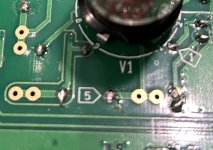
the PCB is ready to use better volume pot...
in order to install ALPS or TKD properly.. you need to cut the dot line of the pcb..
..
in order to install ALPS or TKD properly.. you need to cut the dot line of the pcb..
..
Ok, understood. Thank you Sir for your time.
From couple pictures seems like no need for cutting...
From couple pictures seems like no need for cutting...


Those jumpers control the output voltage, not that much the impedance. The TU-8200R has a 220 Ohm serial resistor at the headphone output (R43/R44), hence the high output impedance at all settings. It must be there to protect your hearing. You can bypass them for low to medium sensitivity headphones, I did that.Thanks for the answer, but the video I watched had that option. However, even on the lowest setting, the impedance was 250 ohm minimum. Do you know the actual impedances corresponding to the High, Med, Low settings and has it changed over the past couple of years?? Cheers and happy new year
I'm trying to figure out why C3-C4 are more "important" in terms of sound than the coupling capacitors C9-C10. Based on the schematic, I would say that C9-C10 would be more decisive in terms of "quality", because it is "between" the anode of the drive tube and the grid of the end tube.
Some explanation: according to hificollective, the effect of the C3-C4 position on the sound is "stronger", at least according to the capacitor recommendation.
Don't trust those sites that much, they want to sell premium components with high margin. C3, C4, C9, C10 are all coupling capacitors between anodes and grids with the same values and importance.
Is there anyone interested Silver LL2777B?
I talked to Per Lundahl this morning. He told me he has enough silver wire to make few Silver OPT (LL2777B)
I talked to Per Lundahl this morning. He told me he has enough silver wire to make few Silver OPT (LL2777B)
I may have bricked my 8200.
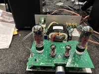
I initially completed the amp, and tested it with the cover off to make sure it was working before completely closing up the amp. It sounded great! Black silence, sweet tube audio. I closed up the amp, and the right inputs on both channels started intermittently coming in/out.
So, I unbuttoned everything and checked the 90 degree solder joints on the 5/6 boards - problems there. I re-joined that set of joints, and re-checked the inputs - looked fine. Re-assembled the amp - no right channels, which worked if I moved the right inputs. So I assumed the jacks had gotten out of spec due to heat from fussy solder joints.
So, as you can see, I decided to get some chassis mount rca jacks and hard wired the inputs directly to unit 2. Continuity check shows good from jacks to solder joints.
However, now I get a continuous hum, that increases in volume when I touch the amp.
Did I kill the amp? Should I buy another kit and start over?
Attachments
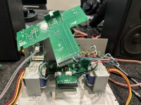
WJM123, are you sure the metal rca sockets don't touch the metal chassis?
What happens if you unscrew the sockets and just leave them hanging? (without the touch anything)
What happens if you unscrew the sockets and just leave them hanging? (without the touch anything)
I dont know your exact issue, but just wanted to say that I dont think you "killed" the amp and starting from scratch sounds pretty overkill... Unless there is some significant damage to the PCB, this should be fixable.
You might have a grounding issue with the new RCA jacks.
Personally, I would undo that and get new PCB mounted jacks.
Then take it apart and review all solder joints and construct it per the manual.
Double-check your voltages and try different input tubes
You might have a grounding issue with the new RCA jacks.
Personally, I would undo that and get new PCB mounted jacks.
Then take it apart and review all solder joints and construct it per the manual.
Double-check your voltages and try different input tubes
I get a small bit of ground hum from the left channel only, which increases when i touch the volume knob. Nothing from the right channel - not sure if black silent or dead. The ground noise does not increase/decrease when I increase the volume.WJM123, are you sure the metal rca sockets don't touch the metal chassis?
What happens if you unscrew the sockets and just leave them hanging? (without the touch anything)
Yes - no changeAnd if you switched the input selector dou you get the same situation?
which leads me to believe it is maybe not the input jacks?
sort of lost as to what it might be; I guess I could take it all apart and start over - but it seems like a lot of useless work if I just don’t know the issue
There is thread with the older version (8200) and there are some idea, fixing, upgrade etc.Yes - no change
which leads me to believe it is maybe not the input jacks?
sort of lost as to what it might be; I guess I could take it all apart and start over - but it seems like a lot of useless work if I just don’t know the issue
One thing: wrap (2-3x) the cable from the AC inlet to the PCB (grey cable with 2 wires on the left on the pictures)
I’m sorry for the delay; are those the numbered “flags” on side B of Unit A? Like this pic?pls send me all test points reference voltages