A 12AX7 would be an excellent test because it's a known quantity (lots of people have tested them). The Cin should be about 200pF or maybe a bit more.
Cgk = 1.7pF + 1pF stray = 2.7pF
Cga = 1.6pF + 1pF stray = 2.6pF
Cgk + Cga(A+1)
2.7 + 2.6 (71) = 187.3pF
Cgk = 1.7pF + 1pF stray = 2.7pF
Cga = 1.6pF + 1pF stray = 2.6pF
Cgk + Cga(A+1)
2.7 + 2.6 (71) = 187.3pF
Some less knowledgeable "designers" just thought they could do it by removing the active RIAA feedback and put it passive between the same 2 triodes 😀
An excellent point. Input stage dynamic capacitance has only become an issue since the current fashion of lossy RIAA between two stages became popular. Old fashioned long loop feedback around two (or two plus a follower) stages to the cathode of the first stage doesn't suffer from this problem. (Input impedance is increased by the ratio of feedback.)
But fashion dominates DIY audio these days, and anything out of fashion is a hard sell.
All good fortune,
Chris
But fashion dominates DIY audio these days, and anything out of fashion is a hard sell.
All good fortune,
Chris
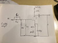
In attach the schematic about test on lab of EF184 in triode.
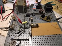
I made a quick circuit as photo.
The 184 is a new Telefunken
The method is to put a R kohm in series with input and a cap in parrallel with R.
This is normally done in the Audioreview lab with a little box with two rotary switches, one for resistors and one for caps
In this way we can check the real Rin and Cin of each electronics under test.
In my case I put the 47kohm ( standard value) as Rx and no Cx .
I sent a 100mV in input to the circuit.
I measured the V at the out at 100 Hz and 1000 Hz with just a minor changes . The Zout of AP SYS Two is 20 ohm .
Then I move to 20 kHz and insert some Cx unitil the read the same value at 100 hz; the value found is the Cin real of 184 in triode mode.
It is around 210 pF +/- 10 pF
I consider +/-10 pf as some parasitic and tolerances.
Walter
Attachments

Some less knowledgeable "designers" just thought they could do it by removing the active RIAA feedback and put it passive between the same 2 triodes 😀
Actually, it's more vacuum tubes vs. solid state.
If using tubes, the open loop gain isn't much, so it's not easy to get great performance from an RIAA EQ implemented within the NFB loop. I goofed around with that back in the days when Van Alstine was modding the Dynaco PAS2/PAS3 phono circuit. The Marantz 7C and EAR 834 also implement the RIAA EQ in NFB loops, with cathode followers to drive the loop. That works, but won't the frequency response and channel-to-channel balance suffer as the tubes age and the open loop gain sags? Aren't there issues with headroom and recovery from loud ticks/pops?
If you use op-amps then the RIAA EQ in NFB loop topology works better. The op-amps have much higher open loop gain than any tube, so will not suffer from wandering gain or frequency response errors from something like tube aging. (Why it's fashionable to use passive RIAA EQ between op-amp stages is a question I can't answer.)
It's never simple, is it.
Last edited:
In attach the schematic about test on lab of EF184 in triode...
...the value found is the Cin real of 184 in triode mode.
It is around 210 pF +/- 10 pF
Walter
Oh boy. That's high. Oh well. Back to EC97, 6GK5, etc. Or a hybrid FET-triode cascode.
I don't think active RIAA is sensitive as you say ... first of all small tubes like 12AX7 are still good from 60's amps , second , negative feedback by definition makes a circuit much less likely to be affected by small changes or mismatches . A passive RIAA is much more affected by this issues .
Actually, it's more vacuum tubes vs. solid state.
If using tubes, the open loop gain isn't much, so it's not easy to get great performance from an RIAA EQ implemented within the NFB loop.
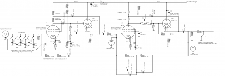
Depends on how many tubes you put in the loop and whether you split the gain over two amplifiers in cascade or try to do it all at once. The attachment has a RIAA conformity of +0.1 dB/-0.2 dB at 1 Mohm load, +0 dB/-0.3 dB at 10 kohm load, 20 Hz to 20 kHz, measured values of the worst of two channels. Because the first stage works in open loop (R5A and R5B are only meant to get a low-noise 47 kohm input resistance), it has maximal Miller effect, resulting in an input capacitance of about 90 pF.
Attachments
2 stages with 12AX7 have an open loop gain of about 4000 or more and can be made to match perfectly RIAA curve .
If we consider 3mV input and 150mV rms out , the gain needs to be just 50 at 1KHz . Plenty of headroom .
If we consider 3mV input and 150mV rms out , the gain needs to be just 50 at 1KHz . Plenty of headroom .
Closed-loop gain of about 500 at 20 Hz, so a loop gain of -8. If you don't correct the RIAA network values for finite loop gain, that will give you a response error of about -1 dB at 20 Hz.
Oh boy. That's high. Oh well. Back to EC97, 6GK5, etc. Or a hybrid FET-triode cascode.
Remember 210pF includes miller. So with 10pF+200pF/28 = 10pF + 7pF.
My setup indicates a bit lower Cin, not so sure his method is more accurate, not enough difference between 100Hz and 1kHz...
The test circuit is simply and efficent
Of course some tolerancs are considered.
Also if you change the brand of the tubes you can have a little differences, just few pF.
The total Cin is the effective value considering a little wire connection, the sockets , etc..
The value found must be added to the cable capaciity so we can reach around 300 pF, less or more.
So it is reasonable for most of the MM head.
Walter
Agree.
We will have some capacitance but I wonder if it's not so bad.
I think perhaps a little less 1st stage gain combined with as short cable as possible can lead to something in the 150-200pF range.
6922 may be the perfect first tube since the gain is medium. 3A5 might be even better. Perhaps 3A5-6EJ7-6922...
For low noise we want most gain in the first stage, but as long as the gain is > 20dB, input noise might not be an issue. It just means we must design the next stage as low noise as well, which we do anyways. At least if input capacitance is important to keep low.
2 stages with 12AX7 have an open loop gain of about 4000 or more and can be made to match perfectly RIAA curve .
If we consider 3mV input and 150mV rms out , the gain needs to be just 50 at 1KHz . Plenty of headroom .
150mV out from 3mV in? That's 34dB gain. You can do that from a couple of 6DJ8 w/ passive RIAA. That's been done a kazillion times.
I aim for 1V out from 5mV in (46dB gain). I like my records to play at about the same level as music playing from my DAC.
The problem with headroom is at the very low end, where impedances start to get high, gain gets lower, and where the most gain is required.
MarcelvdG, that circuit has some nice tricks! I like the bootstrapped pair configuration with EF86 and ECC83 cathode follower. Why an ECC83 as the cathode follower, though? Anode current of 1mA is enough to drive the feedback loop without loading down? V2A is driving V3 with a 23.7k ohm series resistor, which defines the input impedance of V3 once the NFB loop is closed. Isn't that a heavy load for an ECC83 cathode follower? Or is there something else compensating for that?
6922 may be the perfect first tube since the gain is medium. 3A5 might be even better. Perhaps 3A5-6EJ7-6922...
6922 = ECC88 = 6DJ8 = 6N23P
That's a very popular triode for the input stage of an RIAA phono preamp. It might be the best way to go. Cin of about 100pF in most cases. Add 150pF for the tonearm-to-preamp cable and you're at the higher end of recommended load for most MM cartridges.
However, 6GK5 is also interesting. Higher mu (70 on the data sheet), very low inter-electrode capacitances (Cga = 0.52pF). Its input capacitance can be kept down well below 100pF. If it's 75pF (should be achievable) and your input cabling is 100pF (also achievable) you can get the load capacitance down to <200pF, which is within the optimal range for contemporary MM cartridges like Audio Technica, Nagaoka, Ortofon, etc.
Incidentally, if you're using a moving iron cartridge with low coil inductance like a Grado, then the input capacitance is not nearly as big an issue.
Last edited:
An excellent point. Input stage dynamic capacitance has only become an issue since the current fashion of lossy RIAA between two stages became popular. Old fashioned long loop feedback around two (or two plus a follower) stages to the cathode of the first stage doesn't suffer from this problem....
If you go back enough, NFB was not used, it was all passive between stages. See earliest RCA New Orthophonic suggested implementation. (There's an older plan with 6SC7 common-cathode tube, but the basics were the same.)
An intermediate step was NFB from 2nd plate to 1st plate (leaving 1st G-P wide open), such as Fisher 50-PR. (In fact this form does not do the HF EQ until after the 2nd stage, so no effect on the cartridge.)
Attachments
Yes, the bad PSRR of any high internal impedance stage has to be taken care of by a meticulous PSU design (which isn't that difficult, I think).
Best regards!
Or you inject the noise anti phase. You could make a lower tube pentode or triode) under the pentode inject the power supply nose from the B+ Through the grid?
Also couldn’t you simply make the tubes common base with a circlotroneqsue floating power supply? (broskie writes about that here: Even More MC Pre-Preamps)
My old Dyna SCA-35 (a single 12AX7 per channel) phono stage hasn't been used for a while, so is being refurbed, and must be kept to the same single 12AX7 constraint because fashion. And I just want to. For the last 30 or 40 years it's been first stage wide open with battery bias (by elevating the cartridge and connecting cables from signal ground by -1.5 Volts) and second stage RIAA by anode follower, a la C. P. Boegli.
It's worked fine with low-Z Denon DL-160's, but have burned through a lifetime supply in less than a lifetime. Now want to make it compatible with Shure Ultra 500 in case it were to be put back into service, so facing the same design choices as the OP, except very few degrees of freedom.
The classic single 12AX7 phono stage is maybe the most interesting design balance in audio if it must be plug-in compatible with all medium impedance cartridges. The Golden Era designs, even Dyna's original, are very tough to better. There's really no way around feedback to the first cathode to keep input capacitance acceptably low.
If not constrained to a 12AX7, there are lots of better options, like the lovely little Russian pentodes from the 6J9P (6688, E180F) and 6J11P families. Or the 6J51P (EF184, 6EJ7) family, although I'm not as confident in their 1/f performance. Here in the Plague times, all valves need to be sorted for excess noise. But I do not fear the pentode, especially in "BestPentode" operation. More options.
All good fortune,
Chris
An intermediate step was NFB from 2nd plate to 1st plate (leaving 1st G-P wide open), such as Fisher 50-PR. (In fact this form does not do the HF EQ until after the 2nd stage, so no effect on the cartridge.)
That shunt feedback in the second stage reduces the impedance that loads the first stage, so that should reduce Miller effect. An AC grounded first stage cathode also helps to minimize hum due to heater emission or heater to cathode capacitance or leakage resistance ( assuming an AC heater supply).
Last edited:
- Home
- Amplifiers
- Tubes / Valves
- EF184 in triode for phono stage input?