Yes, the bad PSRR of any high internal impedance stage has to be taken care of by a meticulous PSU design (which isn't that difficult, I think).Agreed. But what about PSRR?
Best regards!
It reduces the signal voltage across the grid-anode capacitance and hence the current flowing through it. See the attachment and pretend the JFET is a triode.
Sorry, still don't get it. The document may well apply to SS designs where the input impedance of the »nullator« is low. This reminds me somewhat of the ancient German DUAL TVV 47 RIAA amplifier:

Here the 2nd transistor has a very low input impedance, due to it's lacking emitter resistor. This eliminates the 1st stage's Miller capacitance almost completely, so an additional capacitor C2 needs to be provided.
But in tube amplifiers we usually have high input impedance, hence significant voltage swing in the preceeding stage.
Finally, how can we say that it's the input stage's gain that is reduced by GNFB, if an amplifier has more than this single stage? It is clear that the GNBF signal that is applied to the cathode decreases the impact of the grid to cathode capacitance. But how does it decrease iller capacitance? As I see it, all stages run with the gain given by design, but the amplifier only amplifies the input signal minus the GNFB signal with it's full gain. Am I wrong with my assumption?
Best regards!
In the first part of the document, the input impedance of the second stage is undefined: a nullator has zero voltage across it and zero current through it, and 0/0 is undefined.
In the second part, "Impact of finite gain", the second and later stages are for simplicity modelled as a voltage controlled voltage source, so the open-loop input impedance of the second stage is infinite.
In either case, the signal voltage swing at the drain/anode is much less than the product of the gain of the first stage and the voltage delivered by the cartridge.
Last edited:
To calculate Miller effect you need gain between g1 and anode and that will be affected by gnfb.
For eg, you have 1V signal at g1 and 0,9V gnfb at cathode. That leaves 0,1V to amplify.
If tube gain is say, 50 you have -5V at anode.
That gives 6V difference between g1 and anode, 6 times higher than g1 signal, so Miller capacitance is 6 times Cag1, not 51 as it would be without gnfb.
For eg, you have 1V signal at g1 and 0,9V gnfb at cathode. That leaves 0,1V to amplify.
If tube gain is say, 50 you have -5V at anode.
That gives 6V difference between g1 and anode, 6 times higher than g1 signal, so Miller capacitance is 6 times Cag1, not 51 as it would be without gnfb.
Exactly. I calculated it anticausally, but it boils down to the same thing, and your explanation is probably clearer.
That's very clear, thank you.
The grid-anode *capacitance* (Cga) of the triode remains the same, however the amplification (A) is reduced by NFB, so the resulting input capacitance is reduced by applying NFB, via the resulting gain reduction.
The grid-anode *capacitance* (Cga) of the triode remains the same, however the amplification (A) is reduced by NFB, so the resulting input capacitance is reduced by applying NFB, via the resulting gain reduction.
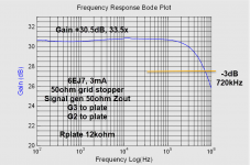
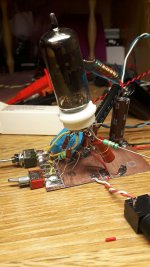
I made a quick circuit and did some measurements. I tried both 39kohm and 12kohm as plate resistors. I tried both normal trioded with G2 to plate, and using just G2 as the plate. I saw no real difference. I also tried G3 to cathode and plate and saw practically no difference.
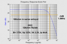
Rp 12kohm with only 100ohm in series with the input, the gain and -3dB are:
Gain 33.5x and -3dB ca 720kHz.
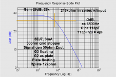
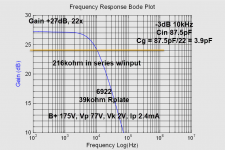
Added 216kohms in series w input:
Gain dropped to 28x (gatebleed 1.15megohm) and -3dB 6500Hz. 216kohms and 6500Hz indicates capacitance of 113pF, and dividing by gain the input capacitance looks like 4pF.
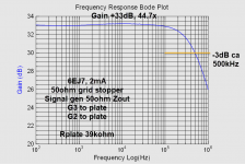
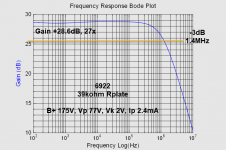
Rp 39kohm with only 100ohm in series with the input, the gain and -3dB are:
Gain 44.7x and -3dB ca 500kHz.
Added 216kohms in series w input:
Gain dropped to 39x (gatebleed 1.15megohm) and -3dB 4500Hz. 216kohms and 4500Hz indicates capacitance of 164pF, and dividing by gain the input capacitance again looks like 4pF.
So I am not sure how accurate this type of testing for input C is, the output C is also playing tricks. But I think I am using high enough series resistance so the input is dominating the -3dB point.
EDIT: I think I need to use the series resistor in parallel with the grid leak for the calculations... 216kohm in parallel with 1.15megohm...182kohm.
That means Cin is 5pF.
Rp 12kohm with only 100ohm in series with the input, the gain and -3dB are:
Gain 33.5x and -3dB ca 720kHz.
Added 216kohms in series w input:
Gain dropped to 28x (gatebleed 1.15megohm) and -3dB 6500Hz. 216kohms and 6500Hz indicates capacitance of 113pF, and dividing by gain the input capacitance looks like 4pF.
Rp 39kohm with only 100ohm in series with the input, the gain and -3dB are:
Gain 44.7x and -3dB ca 500kHz.
Added 216kohms in series w input:
Gain dropped to 39x (gatebleed 1.15megohm) and -3dB 4500Hz. 216kohms and 4500Hz indicates capacitance of 164pF, and dividing by gain the input capacitance again looks like 4pF.
So I am not sure how accurate this type of testing for input C is, the output C is also playing tricks. But I think I am using high enough series resistance so the input is dominating the -3dB point.
EDIT: I think I need to use the series resistor in parallel with the grid leak for the calculations... 216kohm in parallel with 1.15megohm...182kohm.
That means Cin is 5pF.
Attachments

Last edited:
A good RLC bridge has at least 3 digits after 1pF . For testing just the tube without socket , traces/wires influence . I guess this is the way they measure it in datasheets , not in a real circuit .
In datasheets for a pentode Cg1a is very low , typical 0,0x pF . From observation the anode - G1 distance is much higher than in a triode .
In datasheets for a pentode Cg1a is very low , typical 0,0x pF . From observation the anode - G1 distance is much higher than in a triode .
Last edited:
I made a quick circuit and did some measurements... the input capacitance looks like 4pF.
EDIT: I think I need to use the series resistor in parallel with the grid leak for the calculations... 216kohm in parallel with 1.15megohm...182kohm.
That means Cin is 5pF.
First off, thank you for doing this!
By Cin, do you mean Cga? If so...
Cga of 4pF or 5pF for a high mu/frame grid RF triode looks plausible.
Check out the data sheets for 6J4 or 8532. That's a high mu/frame grid RF triode. Its Cga is listed as 4pF, Cgk,h listed as 5.5pF.
6J4 mu is listed at 55, so I figure an in-circuit gain of 40X is reasonable.
6.2pF + 4.7pF(41) = 198.9pF for the total input C after accounting for Cmiller.
A total input capacitance of about 150pF could be accurate for EF184-triode.
--
Lots of great discussion so far. Maybe I could add a background to the input capacitance requirement. A medium impedance (MM, MI, etc.) cartridge is a voltage generator with a large (maybe half a Henry) series inductance followed by the sum of its own (effective) shunt capacitance plus cable capacitance plus preamp input capacitance, and a loading resistor.
That voltage generator is driven by a rock dragged down a plastic groove coupled to the generator by a very long (at this scale) tube. The effective moving mass that must be driven by the wiggles in the groove includes the stylus itself, some portion of the mass of the cantilever, and some contribution from the moving parts of the generating mechanism. Each bit's contribution varies with its distance from the pivot point. Yada, yada.
This (effective, meaning summed and referenced to the stylus contact point) moving mass resonates with the vinyls compliance (it's squashed by many tons per square inch dynamically) near or ideally above the upper limit of hearing. This is the first relevant resonance.
The second relevant resonance is the electrical L/C/R resonance. To hear what a cartridge would sound like without the electrical resonance simply listen to a very low inductance cartridge like a moving coil.
Some will immediately be thinking "Hey! Why not just use a very small resistance load so I don't have to worry about that resonance? Just damp it to nothing special" Absolutely right, but the source's large inductance will make response fall at 6dB/oct starting somewhere in the audio range. "Well then, why not adjust the loading resistor to put that pole at 75uS, and leave that pole out of the preamp?" Again, absolutely right.
National Semiconductors' handbooks of the mid-late-1970's discussed this in their always excellent way. And SY has expanded on the idea both here and on his website, moving the pole up to around 8KHz to optimize noise performance.
All good fortune,
Chris
When the mechanical resonance has a Q above 0.5 sqrt(2) and the electrical resonance has a Q smaller than 0.5 sqrt(2), which is often the case, removing the electrical resonance will give you a peak in the response.
Hans van Maanen solved that in the 1970's by also adding a reverse resonance filter. Steven van Raalte later published a simplified version with improved stability in Linear Audio.
Hans van Maanen solved that in the 1970's by also adding a reverse resonance filter. Steven van Raalte later published a simplified version with improved stability in Linear Audio.
Last edited:
If we had a way to measure these things, fixes would be (with DSP) trivial. Sadly for us, with no ability to generate source vinyl, perfection is reserved for heaven.
As MarcelvdG has pointed out, mechanical resonances are much higher than Butterworth, and electrical resonances are usually slightly lower in conventional (47K Ohm resistive load with textbook RIAA EQ) phono systems.
In the classical solution, transfer response before any electrical filtering includes a less than 6dB/oct falloff caused by geometrical losses from the stylus/groove interface (the stylus is not zero size) and the stylus effective mass / vinyl compliance resonance.
Again in the classical solution, the electrical L/C/R resonance of medium impedance cartridges is used deliberately to (roughly) compensate for geometric losses, and to (at least partially) reduce the response rise from the mechanical resonance. Obviously, that's a tricky combination.
There are no elegant solutions for playing vinyl records. Everything is an engineering balance, and we still have to mop the floors afterwards. Fun! though.
All good fortune,
Chris
Companies like Record Industry in Haarlem can manufacture any test record you like for you (or any other record), but there is a minimum order quantity of 300 records.
Last edited:
My point about vinyl test sources doesn't apply to music releases, but rather to a traceable, definable testing source. For measurement, we have an inherent chicken and egg paradox. How can we know something significant about about a vinyl record without playing it? And how do we play it? Through a mechanical and electrical system. How do we calibrate the mechanical and electrical playback system? With a vinyl record source.
This is a difficult cycle to interrupt these days in the classic ways. In the glory days of vinyl, heavy hitters like Shure, Stanton, B&O, and Ortofon had the money and engineering talent to do fundamental investigations, and we're still using their 1960s, 1970s work today because it hasn't been improved.
In a modern context, a frequency response test vinyl would be some modification of an impulse, maybe an MLS sequence because true impulses are difficult to track and to engrave, even if small and repeated at a regular rate, allowing noise reduction by summing over time. If an MLS proves to be valid in this circumstance, this could be done by a competent music vinyl pressing shop without a lot of drama. Maybe 50 folks interested in vinyl playback could kick in for half a dozen each?
I'm not smart enough to say for sure that an MLS sequence is a valid substitute in this location, but maybe somebody smarter might chime in. Would definitely be interesting to know.
All good fortune,
Chris
To understand at the best the specs of MM or MC Head you have to found the CBS test record and you must have the proper test set.
CBS STR series; I have about t5-6 of them.
Then there are some Bruel&Kijaer, but rare. ( I have also them).
Also the HIFi News test record can help.
There is also a Denon AD-1 LP test, very good but rare
But with Arta sw and a good sound card you can see a lot of info
In photo my collection of LP test.
Attachments

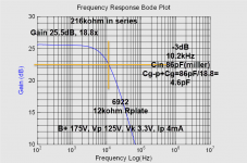
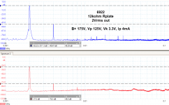
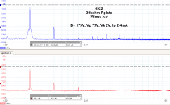
I did some distortion measurements as well, and I had to test a 6922 I had laying on my desk... Mostly for comparisons, but also testing my setup.
Looks like 4-5pF for 6922.
I guess my setup introduces slightly more capacitance than indicated on datasheets. But as has been mentioned, datasheets show the tube out of circuit, in other words unlikely conditions. My circuit is point to point with lots of space between resistors and the gnd plane. I do not think my circuit is very capacitive.
4-5pF is actually not so bad, at least compared to SS, I think it is something to live with, or use cascodes or other means to lower the effective input C.
The FFT shows some 2H on the input test signal, I do not what is causing that. Perhaps the attenuator I am using to adjust the input for 2Vrms output.
Attachments
-
 6922_12k_216kohm.png80 KB · Views: 93
 -
 6922_12k_100ohm.png73.3 KB · Views: 100
 -
 6922_39k_216kohm.png75 KB · Views: 97
 -
 6922_39k_100ohm.png70 KB · Views: 94
 -
 6922_fft2kHz_12kohm.png121.9 KB · Views: 159
 -
 6922_fft2kHz_39kohm.png115.7 KB · Views: 168
 -
 6ej7_fft2kHz_12kohm.png118.1 KB · Views: 167
 -
 6ej7_fft2kHz_39kohm.png113.8 KB · Views: 162
Thanks again for the work you're putting in!
So, if you measured 4pF the EF184-triode, and the 6N23P comes out with 4pF as well, then we can probably assume that they have similar Cga, yes?
According to data sheets, Raytheon 6922 Cga = 1.6pF and Philips ECC88 Cga = 1.4pF
Both of those sheets show Cinput at about 3.6pF
It's conceivable that your test setup has 0.4pF or so of stray C, right?
I guess it's likely that the EF184-triode has similar Cga as a 6DJ8.
I wonder what would happen if you measured a triode with known very low Cga, like 6GK5 or EC97. Those both are supposed to have Cga = 0.52pF
--
- Home
- Amplifiers
- Tubes / Valves
- EF184 in triode for phono stage input?