With a pentode config in a phono you can't get that type of results.
- 82/84 dB of s/n ( weighted) it is very high, this means that the stage is completely "death"
The BestPentode circuit is a creative way to get rid of partition noise, so the noise should be about the same as when the pentode is triode-connected.
For me, the goals for the input stage of a MM phono preamp are
1. Low noise
2. High gain
3. Low capacitance
4. Good PSRR
Everything is a compromise between this and that.
- Pentode has 2 and 3 covered, but not great at delivering 1.
- Cascode has 1, 2 and 3 covered.
For both of the above, 4 is not delivered (bad PSRR). Use an excellent PSU and this is not a problem.
A common cathode triode stage is probably the better compromise.
For common cathode triodes:
- 12AX7 has 1, 2 and 4, but not 3 (Cin = 200pF or so)
- 12AT7 may be a good compromise. 1 = mediocre, 2 = just enough, 3 = mediocre, 4 = ok
- 6DJ8 has 2, 3, 4 covered, but gain is not high (about 24X or so)
- 6GK5, etc. has all the bases covered. (Cin = 75pF or so, gain = 50 or so)
6EJ7-Triode should be good too, but what is its Cin when wired triode? 100pF? 150pF?
D3a-Triode delivers 1, 2 and 4, but 3 is terrible (Cin = 300pF or so)
The target gain for the entire RIAA stage would be about 45dB (1kHz). 5mV input = 1V out
Last edited:
to rangon
I will check the Cin with 184 in triode ( plus some others) ; I need some times to do it. My lab is "suspended" for some time of fun 🙂
I have done the test on freq. response in the past.
Walter
I will check the Cin with 184 in triode ( plus some others) ; I need some times to do it. My lab is "suspended" for some time of fun 🙂
I have done the test on freq. response in the past.
Walter
Thanks. The data sheet is confusing for EF184/6EJ7.
How does the Cg1g2 spec influence Cg1a when the pentode is wired triode? One would think that since g2 is shorted to the anode, Cg1a now becomes the capacitance of g1 to the combined g2 and anode. Since Cg1a is tiny (0.005pF), it will be dominated by the capacitance between the g1 and g2, which is stated to be 2.8pF.
Assuming the triode Cga is 2.8pF, the Cin of the EF184-Triode would likely be
Cgk + Cga(A+1) = 10pF + 3pF(41) = 133pF
That would be OK, but I think I'd use a 6GK5 for the first stage, to take advantage of its very low Cga (0.5pF).
All of this is brought on by my use of a contemporary Audio Technica MM cartridge, of course. It would like to see a load of less than 200pF total. That's very difficult to accomplish with a vacuum tube RIAA stage.
I struggle to find an explanation. What follows are just some thoughts (in which I ignore the possible effects of g3) and what I found on the (or a?) definition of Cg1a.
To me, assuming that Cg1(g2+a) would be dominated by Cg1g2, is like looking at Cg1g2 and Cg2a as if they were two series connected capacitors. In this view Cg2a would be given by:
1/Cg1a = 1/Cg1g2 + 1/Cg2a
1/0.005 = 1/2.8 + 1/Cg2a
200 = 0.35714 + 1/Cg2a
Cg2a = 0.005009 pF
But could this low capacitance between g2 and the anode be true? And what if you would connect g1 with g2? Would ‘C(g1+g2)a’ than be dominated by Cg2a? Would this not create a triode with a very low Cga? I find that hard to imagine.
In a 1946 Philips book Cg1a in a pentode is defined as the capacitance between g1 and the anode, with all other electrodes (f, c, g2, g3) connected to eachother (but not to g1 or the anode). It doesn't say how Cg1g2 in a pentode is defined. Maybe the same principle applies. Than Cg1g2 is the capacitance between g1 and g2, with (f, c, g3, a) connected to eachother. Cg1(g2+a) would than be the capacitance between g1 and (g2+a), with (f, c, g3) connected to eachother.
Last edited:
For triode connection the anode is shorted with G2 so there is no capacitance between ... Cg1a is then in parallel with Cg1g2
Last edited:
I understand that in triode mode the capacitance between g2 and a is shorted. But what is Cg2a in pentode mode? Is that capacitance really only 0.005009pF, so just a fraction higher than Cg1a?
I still doubt if in triode mode Cg1(g2+a) is just Cg1g2 + Cg1a, so 2.8 + 0.005 = 2.805 pF. I don't know if the value of Cg1a is independent of the pentode being wired as a pentode or as a triode. I feel that it has something to do with the way these capacitances are measured but I can't figure it out yet.
Maybe I'll do some measurements on some pentodes today.
2.8pF is pretty high , multiplied by gain because of Miller
ECC83 has Cga = 1,7pF .
In pentode mode there is not Miller effect , then the input capacitance is really low .
ECC83 has Cga = 1,7pF .
In pentode mode there is not Miller effect , then the input capacitance is really low .
Last edited:
For triode connection the anode is shorted with G2 so there is no capacitance between
The capacitance of Cg1g2 = 2.8pF, but what does that mean for the capacitance of g1 to g2+a?
Does the capacitance of g1 to g2 dominate? Or does shorting g2 to a negate the capacitance of g1 to g2?
2.8pF is pretty high , multiplied by gain because of Miller
Yes, if Cga in triode mode is 2.8pF then that means EF184 as a triode isn't as attractive for use as the input stage in a phono preamp.
ECC83 has Cga = 1,7pF .
Yes, that's pretty high too. Cgk = 1.8pF (GE data sheet). ECC83 has achievable gain of about 70, so (and adding 0.7pF for strays):
Cgk+Cga(A+1) is
2.5pF + 2.4pF(71) = 172.9pF
It's usually even higher in real life (measured), around 200pF.
If a EF184-triode has Cga of 2.8pF and Cgk of 9pF, then
9pF + 2.8pF(46) = 137.8pF
Only a slight improvement, not enough to prompt a re-design.
On the other hand, 6GK5 is a frame-grid, RF triode with mu = 78 and Cga = 0.52pF, so Cin would be:
5.7pF + 1.2pF(61) = 78.9pF
THAT is worth a re-design, for use with contemporary MM cartridges.
So the question remains, does the EF184 (with its frame grid), as a triode, have super-low Cin? Its Cg1a spec is a super-low 0.005pF, but its Cg1g2 spec is a rather high 2.8pF.
???
PS - 12AT7 (ECC81) would have about 100pF or so Cin, if used with operating points that yield 45X gain.
6GK5 would give you more gain with lower Cin, so the only reasons I can see to choose 12AT7 over 6GK5 would be if you need to use a currently-made tube or you prefer a twin triode.
--
Last edited:
Any usual triode has significant capacitance , even ECC88 has 1,4pF Cga
Lower mu doesn't make a tube better , you can easily kill the ECC83 gain to camparable level 😀 And RIAA preamplifier with negative feedback should have much lower input capacitance .
But for RIAA most cartridges are designed for this ... even the RCA cables have significant capacitance .
Lower mu doesn't make a tube better , you can easily kill the ECC83 gain to camparable level 😀 And RIAA preamplifier with negative feedback should have much lower input capacitance .
But for RIAA most cartridges are designed for this ... even the RCA cables have significant capacitance .
Last edited:
Yes, but as yet stated, many (most? all??) Audio Technica carts allow just 200 pF of load capacitance.
Most probably a cascode is the best input stage of a tube MM RIAA preamplifier. It can be designed for a gain comparable to a pentode's, but without the pentode noise.
There's a preamplifier by Audio Research (iirc), though, that makes me scratch my head. It features four ECC88's per channel, with both triodes of any tube in parallel. It's 1st stage is a common voltage amplifier, followed by a cascode, and finally a cathode follower. RIAA equalization is done by global NFB. I really don't get why they didn't place the cascode at the input.
Best regards!
With overall negative feedback and a reasonable amount of loop gain, Miller effect doesn't affect the input capacitance anyway.
Why? GNFB reduces the 1st stage's grid to cathode signal voltage, but does it also decrease it's gain?
Best regards!
Best regards!
Sure it does , if the output is 1V with negative feedback instead of 10V then the first stage in consequence has lower gain .
From what I can see, in a triode, input capacitance is directly proportional to gain.
When you put a NFB loop around the triode, its closed loop gain goes down, which also reduces its input capacitance (reduces Miller effect).
- NFB reduces the Cin of the input triode only if you use an RIAA EQ network implemented in a negative feedback loop.
However, RIAA implemented through a NFB loop requires a lot of open loop gain. Tubes (even pentodes) are limited in that department compared to transistors or op-amps. I think it's probably best to leave NFB-RIAA for solid state designs.
At any rate, I'm set on a design with an input stage using a tube with gain of 40X to 60X, passive RIAA network, a second gain stage, and a buffer on the output (either source follower or cathode follower), with the goal of about 46dB total gain (at 1kHz).
I've wired up a simple (sort of RCA-style) 12AX7 > passive RIAA > 12AX7 > MOSFET source follower phono preamp. With my MM carts I notice a bit of high frequency harshness. (To combat this, I deliberately added 470pF in parallel with the second triode stage, to roll off the highs a bit.)
Changing the tube to 12AT7 brings down the gain a few dB, but the high frequencies sound smoother to me. I assume this is because the Cin goes from 200pF from the 12AX7 to about 100pF for the 12AT7.
I'm using the lowest C tonearm cable I have (80pF). Assuming about 100pF Cin for the 12AT7, I figure the sum total Cload on the cartridge is about 210pF or so. Perfect for the Shure and Stanton cartridges, and I think they sound better balanced with the lower Cin of the 12AT7. The gain is high enough, but not quite as much as I would like (records sound lower in level than the audio from my DAC).
I have one of Merlinb's 3-tube RIAA pcbs, which I'm going to wire up with:
12AT7 > all-in-one-go passive RIAA EQ > 12AX7 > 12AT7 cathode follower.
On paper, it looks like I should get 46dB of gain. We'll see how that turns out.
However, the question still remains -- What is the Cin of a EF184 triode wired? It would be great if it turns out to be 100pF or less. >/=40X gain and <100pF Cin with high gm for cheap would be a very good thing.
That's right. AT carts say recommended load = 47k and 150pF (100pF to 200pF). I'm going to take a chance that total Cload of 220pF is low enough not to excite their resonance in the 8kHz to 12kHz region.
Stanton 681 and Shure M35X literature says recommended load = 47k and 250pF.
Shure M44-7 lit says recommended load = 47k and 400pF to 500pF. Maybe that's one to use with 12AX7 phono preamps?
Agreed. But what about PSRR?
--
When you put a NFB loop around the triode, its closed loop gain goes down, which also reduces its input capacitance (reduces Miller effect).
- NFB reduces the Cin of the input triode only if you use an RIAA EQ network implemented in a negative feedback loop.
However, RIAA implemented through a NFB loop requires a lot of open loop gain. Tubes (even pentodes) are limited in that department compared to transistors or op-amps. I think it's probably best to leave NFB-RIAA for solid state designs.
At any rate, I'm set on a design with an input stage using a tube with gain of 40X to 60X, passive RIAA network, a second gain stage, and a buffer on the output (either source follower or cathode follower), with the goal of about 46dB total gain (at 1kHz).
I've wired up a simple (sort of RCA-style) 12AX7 > passive RIAA > 12AX7 > MOSFET source follower phono preamp. With my MM carts I notice a bit of high frequency harshness. (To combat this, I deliberately added 470pF in parallel with the second triode stage, to roll off the highs a bit.)
Changing the tube to 12AT7 brings down the gain a few dB, but the high frequencies sound smoother to me. I assume this is because the Cin goes from 200pF from the 12AX7 to about 100pF for the 12AT7.
I'm using the lowest C tonearm cable I have (80pF). Assuming about 100pF Cin for the 12AT7, I figure the sum total Cload on the cartridge is about 210pF or so. Perfect for the Shure and Stanton cartridges, and I think they sound better balanced with the lower Cin of the 12AT7. The gain is high enough, but not quite as much as I would like (records sound lower in level than the audio from my DAC).
I have one of Merlinb's 3-tube RIAA pcbs, which I'm going to wire up with:
12AT7 > all-in-one-go passive RIAA EQ > 12AX7 > 12AT7 cathode follower.
On paper, it looks like I should get 46dB of gain. We'll see how that turns out.
However, the question still remains -- What is the Cin of a EF184 triode wired? It would be great if it turns out to be 100pF or less. >/=40X gain and <100pF Cin with high gm for cheap would be a very good thing.
Yes, but as yet stated, many (most? all??) Audio Technica carts allow just 200 pF of load capacitance.
That's right. AT carts say recommended load = 47k and 150pF (100pF to 200pF). I'm going to take a chance that total Cload of 220pF is low enough not to excite their resonance in the 8kHz to 12kHz region.
Stanton 681 and Shure M35X literature says recommended load = 47k and 250pF.
Shure M44-7 lit says recommended load = 47k and 400pF to 500pF. Maybe that's one to use with 12AX7 phono preamps?
Most probably a cascode is the best input stage of a tube MM RIAA preamplifier.
Agreed. But what about PSRR?
--
Last edited:
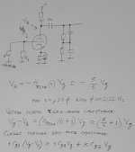
If you get rid of the resistor that's typically placed between the first stage and the RIAA network and change the RIAA network impedance accordingly, you get an inaccurate first pole, but you also get a rolling off gain of the first stage. Miller effect then gives you a shunt resistance instead of a capacitance, and you can correct for that by increasing the 47 kohm resistor. Hopefully the schematic will show what I mean.
Attachments
Last edited:
Suppose you have a Cga of 2.8 pF, a gain of -70 at low frequencies and that you only realize the 75 us time constant with a capacitor that loads the first stage. K is then 933 333.3333... rad/s and the term K Cga then represents a conductance of 2.61333... uS, or a shunt resistance of 382.6530612 kohm. Change R1 to 53.6 kohm and the input resistance is 47 kohm again. With the complete correction done like this, the extra conductance will be negligible, so you won't even have to change the 47 kohm.
- Home
- Amplifiers
- Tubes / Valves
- EF184 in triode for phono stage input?