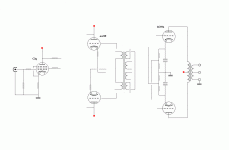
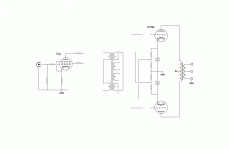
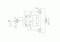
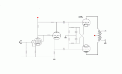
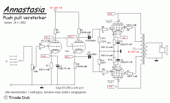
Oh, please stop calling it the Blumlein garter, Blumlein never used it! It was patented by Martens in 1949 (FR64203), and transformer coupled versions even earlier (US2204578). But Blumlein had nothing to do with it!😛
[/rant]
dont know if it matters, but I just found that Alan Blumlein died in a test flight crash 1942
I guess that explains a lot
why he isn't known for the ultra linear coupling
and why it was republished and patented, some time after The War, by David Hafler and Herbert Keroes
shoot, Blumlein actually patended the 'Long Tail Pair', 1936
long tail pair, basic differential amplifier...and phase splitter
pretty expencive to place an interstage in front of that
well, I guess nothing wrong with learning a bit about interstage trafos
ahh, the comment, get back to your ecc99 LTP
thanks Shoog 😛
more to study
but a thing or two are beginning to get through my thick scull
schematics that appeared to me like a total mess, a couple of years ago, is now suddenly beginning to make sense
and still only scratching the surface
but its nice enough
pretty expencive to place an interstage in front of that
well, I guess nothing wrong with learning a bit about interstage trafos
ahh, the comment, get back to your ecc99 LTP
thanks Shoog 😛
more to study

but a thing or two are beginning to get through my thick scull
schematics that appeared to me like a total mess, a couple of years ago, is now suddenly beginning to make sense
and still only scratching the surface
but its nice enough


I'm bowing out with this one
well, If someone could tell me why I placed a cap in one leg of the interstage, or maybe why it shouldnt be there, or which kind of cap, that would be nice
🙂
btw, found this about calculating interstage, by Benny Glass FAQ on interstage and line output transformers (Lundahl)
Attachments
I place phase splitting transformers on the input - because these types perform as well as interstagers for phase splitting - but cost a lot less. I place a LTP after them to achieve the maximum gain from the LTP (twice the gain with both LTP inputs driven). The LTP will also be more accurate if it has both inputs driven. If you are feeling adventurous then direct couple to the finals. In this way you can build an amp with only the power supply caps in the signal path.
Personally at this stage - I think you are thinking about this way to much. Each of the different configurations is relatively easy to try by a simple shift in wires and that way you can actually listen to what difference the different configuration make.
There's nothing like experience for proving a theory.
Shoog
Last edited:
I hear you Shoog, time to build
and some more to study http://www.diyaudio.com/forums/tubes-valves/76820-idea-2-tube-6080-pp-amp.html
and some more to study http://www.diyaudio.com/forums/tubes-valves/76820-idea-2-tube-6080-pp-amp.html
If they dont work out in this project 1K6 is perfect for a 6AS7 amp.
Shoog
Circlotron, maybe ?
read claims that a Circlotron design needs much lower impedance OPT
from half to a quater of normal pushpull 😕
not that I think I'm capeable of doing that
and might not make sense with this low power, or ?
but could still be worth a study
ok, been reading though several tutorials about phase splitters
and if I say more about that it will probably be rubbish
I will try the 'simple' version first
question
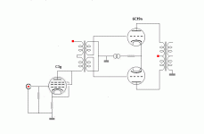
6C19n in PP is supposed to do up to about 10watt in class AB
the sweet thing is that lower impedance 1K6 trafo I happen to have was suggested for this especially
but also read that AB works only with fixed negative bias
is this true ?
or only related to multiple grid tubes, and not triode ?
and triode for classA only ?
another issue is that with fixed bias 6C19n needs about -90V
and that is also said to be problematic
I guess because of relatively low anode/plate voltage
btw, if anyone want to search further, look up 6as7 designs
6C19n is said to resemble half of a 6as7, or at least close
Attachments
If it is half of a 6AS7 then I run mine at 100V 100mA which requires just 30V drive for full output. Running these pass regulators at high voltage is the wrong way to go in my opinion.
Shoog
Shoog
This picture can be used to approximate what to expect from 6S19P. On 100 MA and zero grid voltage voltage drop between anode and cathode will be 50 Volt. That means, on 100V of B+ you get no more than 100V of voltage swing, that means 35V of RMS AC. About 1.2W of output power. Is it enough for 10W dissipation? Up to you. I would consider 200-250V B+ for it, with fixed bias.

I am running mine at about 220V, 45mA as a diff. pair with individual CCS's and cathodes AC coupled.The bias comes out at about 75V. I would not really consider 6S19P to be half of a 6AS7 exactly.
I am running mine at about 220V, 45mA as a diff. pair with individual CCS's and cathodes AC coupled.The bias comes out at about 75V.
It is the same conclusion I come to: to run them as a diffpair, in this exact regime.
I was also thinking that a similar regime would be good for trioded 6P41S; with the same B+ and CCS the bias would come out lower and the anode dissipation appropriately higher. I imagine, Anatoliy, that you might run these tubes a bit harder?
thanks guys, for the hints and pointers
diff.pair
I take it you are suggesting ccs feed to each output anode/plate
as in PPP, parafeed pushpull
hmm, and fixed bias would be applied to IT/CT
or else scrap the IT, and go back to ecc99 phase splitter
and place input trafo in front of it instead
things to think about, again
yeah, I have been tempted by that, so it sounds good to me, if I can handle it
I was also thinking that a similar regime would be good for trioded 6P41S; with the same B+ and CCS the bias would come out lower and the anode dissipation appropriately higher. I imagine, Anatoliy, that you might run these tubes a bit harder?
Yes. I would consider up to 20W per trioded 6P41S.
...also I am going to try them in right-handed connection.
- Home
- Amplifiers
- Tubes / Valves
- ecc99 - 6C19n PP, (6S19P)
