This pop on /pop off is common and has it´s cause in the rail voltages rising unequal, not only at the power supply, but also in the circuit´s current path.
To avoid it electronically is complicated, so the usual approach is to use a relay in the speaker path. If you go for one of the "ususal" PCB solutions, most inklude a DC protection, that kicks in if one of the output semi conductors fails or one rail voltage is missing. Beside from the relay, there are MOS solutions.
IMO a MOS solution is somehow to question, as I do not like another transistor in the signal path.
A relay is not much better, as over time, it builds up resistance at its contacts. In most cases, after only a few switching events under load, the relay does not sound neutral any more. There is no contact, not even expensive ones, that will not build up oxide after a while. Trust me!
So on some of my amps, I accept such a "thump" at power on and a squeaking sound when turning it of. The risk of burning a speaker is addressed in another way, using a conventional fuse in the power supply. This is a very special construction I will not explain here.
So what can you do to not risk your speaker and still not degrade sound? In practice, old amps sometimes sound terrible, only because of burned of loudspeaker protection relays. Replacing them restores sound, until they are used up, again. If you measure distortion before and after replacing, you will be astonished what that simple contact produced in % THD.
So any solution?
If we have a look at relays, we will find it is impossible to make two contacts switch at the same time. There is always one hitting first. So if we use two relay contacts or, even better, two separate relays, one contact will always be the first to conduct. This contact will burn off and develop a resistance (causing distortion in sound), while the second contact will stay perfectly clean. With such a construction, even after some hard switching and years of service, you will not hear any resistance and measure distortion in front and behind the relay just the same.
So, take two stereo PCB`s with such a universal "loudspeaker protection" and use them in parallel, one for each channel. This way you will not have any "thump" problem any more and no relay induced losses in sound quality.
You can integrate an additional relay into an existing protection as well, an even better way.
This pop on /pop off is common and has it´s cause in the rail voltages rising unequal, not only at the power supply, but also in the circuit´s current path.
To avoid it electronically is complicated, so the usual approach is to use a relay in the speaker path. If you go for one of the "ususal" PCB solutions, most inklude a DC protection, that kicks in if one of the output semi conductors fails or one rail voltage is missing. Beside from the relay, there are MOS solutions.
IMO a MOS solution is somehow to question, as I do not like another transistor in the signal path.
A relay is not much better, as over time, it builds up resistance at its contacts. In most cases, after only a few switching events under load, the relay does not sound neutral any more. There is no contact, not even expensive ones, that will not build up oxide after a while. Trust me!
So on some of my amps, I accept such a "thump" at power on and a squeaking sound when turning it of. The risk of burning a speaker is addressed in another way, using a conventional fuse in the power supply. This is a very special construction I will not explain here.
So what can you do to not risk your speaker and still not degrade sound? In practice, old amps sometimes sound terrible, only because of burned of loudspeaker protection relays. Replacing them restores sound, until they are used up, again. If you measure distortion before and after replacing, you will be astonished what that simple contact produced in % THD.
So any solution?
If we have a look at relays, we will find it is impossible to make two contacts switch at the same time. There is always one hitting first. So if we use two relay contacts or, even better, two separate relays, one contact will always be the first to conduct. This contact will burn off and develop a resistance (causing distortion in sound), while the second contact will stay perfectly clean. With such a construction, even after some hard switching and years of service, you will not hear any resistance and measure distortion in front and behind the relay just the same.
So, take two stereo PCB`s with such a universal "loudspeaker protection" and use them in parallel, one for each channel. This way you will not have any "thump" problem any more and no relay induced losses in sound quality.
You can integrate an additional relay into an existing protection as well, an even better way.
yes very good Turbowatch - my past was the same experience with ralay contacts. very nice explanation and solution.
thank you
chris
Another effective way to avoid clicks: use a decent SMPS.
No turn on/off clicks here with my SMPS (specified starttime 200msec) and of course no relays and/or additional protective circuitry.
No turn on/off clicks here with my SMPS (specified starttime 200msec) and of course no relays and/or additional protective circuitry.
Thanks for a thorough explanation Turbowatch, however I read it after installing the one stereo protection board I had. It works as it should and kills any thump/pop for now, but now I'm afraid it might have altered the sound (I didnt notice if it did for now).
My amp layout is now less than ideal though, since I never planned for such a protection board in the first place, live and learn. I will probably re-do this whole amplifier in another enclosure in the future so this will be taken into account.
Now you said this was caused by the fact there was no mute pin, am I correct in assuming a LM3886 (which has a mute pin) properly implemented would not do any on/off pop?
Thanks everyone.
Thanks for a thorough explanation Turbowatch, however I read it after installing the one stereo protection board I had. It works as it should and kills any thump/pop for now, but now I'm afraid it might have altered the sound (I didnt notice if it did for now).
My amp layout is now less than ideal though, since I never planned for such a protection board in the first place, live and learn. I will probably re-do this whole amplifier in another enclosure in the future so this will be taken into account.
Now you said this was caused by the fact there was no mute pin, am I correct in assuming a LM3886 (which has a mute pin) properly implemented would not do any on/off pop?
Thanks everyone.
Hi Joey
the relay contact do not die after some on/off cycle but over years yes. normally you switch on the amp once per day and listened as long as possible😉🙂
a lot of chip amps- except lm1875 (lm1876, lm3886...etc..TPA3250, TPA3255) have a mute pin and a circuit - loading a capacitor- to keep the mute pin active until the power is on the max rail of the chip.
for the LM1875 i can live as rabbitz wrote...no problem...its annoying
chris
Another effective way to avoid clicks: use a decent SMPS.
No turn on/off clicks here with my SMPS (specified starttime 200msec) and of course no relays and/or additional protective circuitry.
Hi fdenys,
Was that with legit LM1875s or the "fake" ones? Cause judging by this thread those fake ones apparently didn't pop.
Another effective way to avoid clicks: use a decent SMPS.
No turn on/off clicks here with my SMPS (specified starttime 200msec) and of course no relays and/or additional protective circuitry.
yes fred nearly all modern SMPS have a "inrush current limiter" and this give the rail supply time to go up before we can hear a the amps outpus something . ideally🙂
chris
Another beginner post Im affraid.
Could you guys confirm if my grounding is ok?
- All the connectors are insulated from chassis.
- I have the safety earth from the IEC tied to a ground lug that grounds the chassis by a short lenght of wire.
- I have the 0 volt at the output of my power-supply board tied to the same lug by a lenght of wire.
- All my standoffs are made of aluminum thus in contact with the chassis (if that matters).
I was testing from my computer using a USB interface until now, but last night I plugged my computer on a HDMI to VGA converter and it started humming pretty bad in the speakers. I dont have that kind of issues with this converter plugged in and my Technics amp.
Last edited:
Do not connect the audio ground to the chassis ground. This will always lead to hum with other grounded connections, like a PC supply.
It may be necessary to use some kind of modified audio to ground connection, like a 15 ohm resistor in parallel to a .47 uF 400V film foil capacitor.
You have to try.
It may be necessary to use some kind of modified audio to ground connection, like a 15 ohm resistor in parallel to a .47 uF 400V film foil capacitor.
You have to try.
I was testing from my computer using a USB interface until now, but last night I plugged my computer on a HDMI to VGA converter and it started humming pretty bad in the speakers. I dont have that kind of issues with this converter plugged in and my Technics amp.
Could be the Technics doesn't have an earth which is common on a lot of commercial amps. All my Yamaha amps have no earth on the IEC socket.
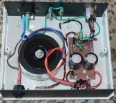
I've added some pics of my power supply and power amp and the grounding can be followed with the green wires.
Earth > chassis
Power supply transformer CT > power supply ground (after caps)
Power supply ground > chassis (earth connection)
Power supply ground > power amp ground (DC in)
Heatsink to power amp ground
Signal and speaker ground all isolated from the chassis
Some builders have the power supply floating with no ground from the power supply going back to earth but I've never used that. Hum can sometimes be cured by using a 10R resistor with parallel reverse diodes in the line from power supply ground to chassis ground (earth). See post #78 in this thread.
Odds are the the video side of things can be causing the issue and it's very common to get hum when running audio from a TV. I suppose it's similar with your HDMI from the computer. Some USBs have a ground lift and on several DACs I've seen has a switch for this.
Usually I find a solution with a cable with alligator clips but it's trial and error but when found it's usually the bleeding obvious.... doh!
Hope you sort it out.
Attachments
Hmm... i re thinking this GND - earth
Turbo wrote that the audio GND should not be the Earth-GND. but if you look at my way i found then we have it at this board. may i am wrong??
path:
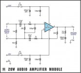
at this board the signal (left side at rabbitz pic) and GND is normally connect via 10R to pcb GND. see picture of the schematic.
we decided to omit this and insert a jumper and we were all happy with this. as rabbitz did this and visible at this picture.
if you check with your DMM between supply GND (+V-GND -V)and the terminal of the input signal GND with your Beep - he will here its connected.
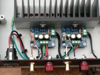
rabbitz pic:
if you follow the GND of the supply terminal - green cable you can see at the left board 3 cables. 1 goes to the right board - ok
second goes to the heat sink - ok
third goes to the XLR connection = the power supply is in a other housing
but there is the earth connected to earth. so singal GND is at earth
metall housing should be earth by safety reasons.
so if you use a metal housing and the Center tab of the transformer should be Supply GND and this GND should be earth connected ---> then we have earth at GND and therefore at signal GND.
may i am wrong???
chris
Turbo wrote that the audio GND should not be the Earth-GND. but if you look at my way i found then we have it at this board. may i am wrong??
path:
at this board the signal (left side at rabbitz pic) and GND is normally connect via 10R to pcb GND. see picture of the schematic.
we decided to omit this and insert a jumper and we were all happy with this. as rabbitz did this and visible at this picture.
if you check with your DMM between supply GND (+V-GND -V)and the terminal of the input signal GND with your Beep - he will here its connected.
rabbitz pic:
if you follow the GND of the supply terminal - green cable you can see at the left board 3 cables. 1 goes to the right board - ok
second goes to the heat sink - ok
third goes to the XLR connection = the power supply is in a other housing
but there is the earth connected to earth. so singal GND is at earth
metall housing should be earth by safety reasons.
so if you use a metal housing and the Center tab of the transformer should be Supply GND and this GND should be earth connected ---> then we have earth at GND and therefore at signal GND.
may i am wrong???
chris
Attachments
Last edited:
Thanks Rabbitz for the info, my current grounding scheme is very much like yours. I will try the 10R + diodes trick.
You are correct, none of the amplifiers I own have an earth ground lug, vintage Technics, my modern NAD, but also tuners, cd players, DAC, interfaces, even my laptop.
I tried removing the link between 0v at PS output and chassis, it makes the hum worse. That allowed me to play a bit with the ground and try it elsewhere but I then noticed I had a far worse hum in one speaker than the other.
1 step forward 2 steps back right? Well the changes I had to go into to wire the speaker protection board indeed messed up the layout and made it that the audio outs of the left channel now have to cross some 120v wires....
If it wasnt for the annoying pop off Id just rip that board out, seems like its causing me more trouble than it solves.
Another test for tonight : testing if the power supply board's mouting holes are linked to ground and/or 0v. Its a kit I got off ebay so you never know.
Thanks,
-Joey
Sorry Chris, I missed your post before posting mine. I also have the jumper there... So the boards themselves would be linking signal ground to earth ground is what youre saying?
Edit: Well they sure link 0V with Signal GND, which is then grounded to earth at the PS.
Edit: Well they sure link 0V with Signal GND, which is then grounded to earth at the PS.
Last edited:
Seems Rabbitz already talked about the 10R :
That post was a long time ago but interesting nonetheless...
The 10R is a ground lift resistor which sits between signal ground and power ground and can help reduce hum but have not seen it used on any of the Chipamps I've build but have on plenty of SS amps.
That post was a long time ago but interesting nonetheless...
Good evening
i am not sure ...so should we implement that what Turbo wrote?
instead of the R2 (actually we have a jumper here) a cap and a resistor:
15 ohm resistor in parallel to a .47 uF 400V film foil capacitor.
so we can keep that 10R resistor and add a 400V 0,47µF
good night
chris
i am not sure ...so should we implement that what Turbo wrote?
instead of the R2 (actually we have a jumper here) a cap and a resistor:
15 ohm resistor in parallel to a .47 uF 400V film foil capacitor.
so we can keep that 10R resistor and add a 400V 0,47µF
good night
chris
Ive tried the reversed diodes + 10r trick, it didn't seem to change anything vs the hum or hdmi adapter being plugged in. In fact the protection board shuts off when I plug in the adapter. I rkn I have something weird happening at my bench.
Now I'm pretty convinced the hum I experience is from poor layout, since it comes from the left board only and this one has output wires going near 120v. Interestingly, the hum is only there when I use my audio interface, it's not there when I use the headphone/line out from my laptop.
I have a chassis on order, I will do my best to make a better layout. I never planned for a protection board so it kinda messed with my plans, and I cannot tolerate the pop off, so protection board it is, or I switch to lm3886.
Interesting fact, my regulated supply has 80mv peak to peak ripple on both rails, but as soon as I plug in the protection board it jumps to 140mv... weird eh?
I'm starting to doubt the protect board, a lot.
Does it hum with the HDMI / VGA adaptor without the protection board? Where does the protection get it's ground and power? Video equipment can be a pain with audio.
The signal ground will go back to earth as does all the 0V wiring (power, speaker, signal). A quick check with a DMM shows this to be the case. I'm no expert on this but doesn't the 0V become the reference (maybe not the right term) for all voltages whether AC or DC. The amp 10R ground lift resistor is not necessary and I have only had it on a few SS amps (e.g. AKSA). All grounds AFAIK should go back to a single common point.
The point I was making before is the RCA inputs need to be isolated from the chassis or you can get ground loops.
BTW, none of my fake chips had the turn off pop only the genuine TI LM1875.
Last edited:
Does it hum with the HDMI / VGA adaptor without the protection board?
I have 2 kinds of noise/hum. One is a loud crackle when I plug in the HDMI adaptor that then turns into a loud humming. This one happened before the protection board. With the protection board in the circuit, if I plug in the HDMI adaptor the protection kicks in and shuts the relays. So I cannot use the amp with the adaptor plugged into my laptop either way.
Theres also the 60hz hum on the left channel, this started happening when I added the protection board and changed the layout to do so. So it could be picked up by the extra wiring needed to get to the board, or on the board itself. The left channel relays are coincidently the closer to the transformer here. But this happens when I use my USB powered audio interface and didn't seem to happen when using the stereo jack out of my laptop. Sadly I dont have any other volume-controlled sources I could try to use.
It's hooked up at the output of my power supply, positive rail and 0v.Where does the protection get it's ground and power? Video equipment can be a pain with audio.
The RCA inputs and speaker terminals are all isolated from the chassis.The signal ground will go back to earth as does all the 0V wiring (power, speaker, signal). A quick check with a DMM shows this to be the case. I'm no expert on this but doesn't the 0V become the reference (maybe not the right term) for all voltages whether AC or DC. The amp 10R ground lift resistor is not necessary and I have only had it on a few SS amps (e.g. AKSA). All grounds AFAIK should go back to a single common point.
The point I was making before is the RCA inputs need to be isolated from the chassis or you can get ground loops.
BTW, none of my fake chips had the turn off pop only the genuine TI LM1875.
I didnt try the fake ones, I assumed I would get better performance from the TI ones.
As always, thanks a lot for your help. Ive listened to the amp all night and felt it is pretty capable!
Hmm... i re thinking this GND - earth
Turbo wrote that the audio GND should not be the Earth-GND. but if you look at my way i found then we have it at this board. may i am wrong??
path:
at this board the signal (left side at rabbitz pic) and GND is normally connect via 10R to pcb GND. see picture of the schematic.
we decided to omit this and insert a jumper and we were all happy with this. as rabbitz did this and visible at this picture.
if you check with your DMM between supply GND (+V-GND -V)and the terminal of the input signal GND with your Beep - he will here its connected.
rabbitz pic:
if you follow the GND of the supply terminal - green cable you can see at the left board 3 cables. 1 goes to the right board - ok
second goes to the heat sink - ok
third goes to the XLR connection = the power supply is in a other housing
but there is the earth connected to earth. so singal GND is at earth
metall housing should be earth by safety reasons.
so if you use a metal housing and the Center tab of the transformer should be Supply GND and this GND should be earth connected ---> then we have earth at GND and therefore at signal GND.
may i am wrong???
chris
pump it up...
It is impossible to give any advice without seeing the installation. Clean pictures can help, if they show all details. No blurred phone pics in the dark...
Make yourself a sketch of all components and all ground connections. This way you can see where you installed the loop.
Use a digital multimeter to find any "invisible" ground path like the mechanical connections.
Try and error will not get you any where. Use paper and brain!
Reduce the components to the minimum, place the transformer 30cm away from the rest, make a connection only from 3 wires twisted together. Later you can move it closer to find a good position.
Mind shielded wires! Don´t earth the shield on both sides. Connect the earth of both input RCA and return only one wire to the central or signal earth.
Get rid of the "protection board", it uses earth and if you connect both amp boards, you will get a loop.
Any PC connection is a ground problem. A major electronic installation like a TV too, as it has an earth potential different from that of the amp. Some connections can only be fixed by using a transformer or an optical, digital output. Last thing is most neutral to sound.
In 9 from 10 cases the hidden ground loops the installer does not see are the problem. There are no amps that can not be silenced talking of hum. The solutions are always simple, usually no need to buy expensive parts like filters.
- Home
- Amplifiers
- Chip Amps
- eBay mono LM1875 kit