(Mod note... thread split from here:
Beginner's Gainclone, HiFi LM1875, The Amplifier Board)
-----------------------------------------------------------------------------------------------
Hmmm Been looking at this as well.
Couple of points;
I located the 'Original'.. and quite good actually..design (haodiy.net) of the currently widely available on ebay, as the 'cloned' 2$ lm1875 'kit'.
PCB layouts..Amp and PS are downloadable at haodiy.net..for DIY PCBs.
Ebay Vultures have shrunken the pcb tho (cheaper to make).. but it's still a good usable layout .. absolutely so for the price 😉
Their Odd low quality parts / value substitutions are definitely for the trash bin though. Just use the pcb.
Daniels' final circuit, seems as oddly complex.. IMO .. with 24 parts.
Certainly seems so as compared to the often described as 'excellent' ESP layout which uses Far fewer parts (15).
Note though that Both the Hao design author And Rod Elliot (esp)both state that the 1875 approaches High end audioweenie sound.. but does not quite achieve it.. all claims aside
Your choice... Suggest trying either the Haodiy OR the ESP circuit as experiment, then comparte Could be interesting and worth reporting back on it?
Last edited:
hi
you mean this board as this thread?:
LM1875 Amp layout
its the board which John audio tech tested...
chris
you mean this board as this thread?:
LM1875 Amp layout
its the board which John audio tech tested...
chris
Last edited:
Yess... But.. John Audio tested it with it's then supplied Recycled genuine 1875 chip ... A rarity indeed.
Still.. it's crippled by the ..significantly different.. ineptly substituted / cost reduced .. cap values.
A departure from the still available Haodiy schematic and pcb design.
Ie; the input caps were designed as 2.2 uf and 22 uf , both 16 v NP types ( or Films.. if the builder could afford it) DIYers en chine often have budgetary constraints.
Should really read the Haodiy.net build article.. It has interesting info and a decent Power Supply design /PCB .
No mention of 'Protection' circuitry tho 😀.
Last edited:
That eBay kit caught my interest as the PCB looks quite good so I'll buy a pair. The first thing to do is throw away all the parts and buy them from a reputable supplier such as Digikey etc.
The circuit uses a schematic from the Silicon Chip "Schoolies Amp" but some of the values on the PCB are different. Maybe better to use another schematic such as:
A. TI typical applications schematic
B. ESP P72
C. The one in this thread (I haven't read the full thread so I don't know if the parts count would suit)
D. Gobo LM1875
E. Chipamp.com used to have one but can't see details now
F. Some other circuit
Attachments
Y
Should really read the Haodiy.net build article.. It has interesting info and a decent Power Supply design /PCB .
http://www.haodiy.net/a/jishuwenzhang/houjiDIY/2014/0617/7340.html
That's a copy from the Silicon Chip article Dec 2004.
Silicon Chip Online - Schoolies Amp
I would like to compare the sound from the one on this thread (already made) with the sound from ESP P72.
Could you please help with the exact placement of components (ESP P72) on the ebay PCB from post #857?
Could you please help with the exact placement of components (ESP P72) on the ebay PCB from post #857?
Just compare the ESP P72 schematic and the one from Silicon Chip link in post #858 and it falls into place on the PCB.
I have off course compared the 2 schematics.
What about R3 on the P72 and the 1K on the schoolies amp....seems to me on different places???
And instead of the 10 ohms on the schoolies amp it should be shorted???
What about R3 on the P72 and the 1K on the schoolies amp....seems to me on different places???
And instead of the 10 ohms on the schoolies amp it should be shorted???
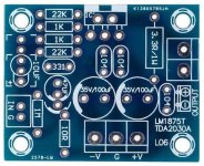
Hi Rabbitz
I have the amp as you posted in #857
my uncoverd topics are: (from left to right)
the 10µF input cap is wrong polarized- but nevertheless we should use a foil cap.
the 47µF is the electrolytic cap for the PIN 2: at the other schematic´s its a 22µF non bolarized cap.
right/upper corner: the 3R3 is marked on the pcb but it should be a 1R resistor. 1W minimum
the supply electrolytic caps are not correct (100µF) because it should be 220µF at minimum on the supply
all other part i measured with my LCR meter and they are ok.
btw: at my kids the 1M and the 10R are missing - i claimed the seller....will see..
wating for power supply and then start with tests...
chris
Last edited:
I have off course compared the 2 schematics.
What about R3 on the P72 and the 1K on the schoolies amp....seems to me on different places???
And instead of the 10 ohms on the schoolies amp it should be shorted???
R3 and the 1K are in the same place just before pin 1 on the chip. The location of the 330pF cap makes no difference for this resistor. The 10R is a ground lift resistor which sits between signal ground and power ground and can help reduce hum but have not seen it used on any of the Chipamps I've build but have on plenty of SS amps.
Hi Rabbitz
I have the amp as you posted in #857
my uncoverd topics are: (from left to right)
the 10µF input cap is wrong polarized- but nevertheless we should use a foil cap.
the 47µF is the electrolytic cap for the PIN 2: at the other schematic´s its a 22µF non bolarized cap.
right/upper corner: the 3R3 is marked on the pcb but it should be a 1R resistor. 1W minimum
the supply electrolytic caps are not correct (100µF) because it should be 220µF at minimum on the supply
all other part i measured with my LCR meter and they are ok.
btw: at my kids the 1M and the 10R are missing - i claimed the seller....will see..
wating for power supply and then start with tests...
chris
Hi Chris
I've yet to decide what values I will end up using as still researching.
I'll be using a 1uF film cap on the input. I've seen various sizes for the feedback cap... TI has 22uF, P72 has 47uF, Gobo has 22uF BP, SC has 47uF. I've still looking at what I will use, but a lot recommend bipolar such as Nichicon ES or a very good Nichicon audio cap. For the zobel, TI and SC has 1R + 220nF, P72 has 10R + 100nF but I'll use 2R7 + 100nF as per my other Chipamps. Most LM1875 I've seen including TI have supply caps at 100uF but some do have 220uF. My power supply will be in a different case so I will add 2200uF caps in the amp case as that was recommendation from a previous build so I will use 100uF I think.
I still have to see if I need a Thiele network (L//R) on the output as have done that on most of my other amps.
Hi rabbitz
this is my first chip amp so i just compare the TI datasheet and the chinese "interpretation". so i have no experience and measurements....i read and learn
i will use the 3R3 at the output
as input cap i will use a 4,7 Wima MKS
the missing 1M and 10R i have on hand - the 220µF too
i will try the electrolytic 47µF at the feedback...first try...
we will see...😉
chris
Hi
The schematic of Gobo, schoolies ...are different to the TI datasheet at the inverted input of the amp....why is that "better?"
hmm. maybe the bipolar is the correct cap here...
chris
The schematic of Gobo, schoolies ...are different to the TI datasheet at the inverted input of the amp....why is that "better?"
hmm. maybe the bipolar is the correct cap here...
chris
My amp (with the same pcb´s as yours) came with a bipolar at the input. I am looking at the IT scheme and they also use a bipolar (1uF) here too.
http://www.ti.com/lit/ds/symlink/lm1875.pdf
http://www.ti.com/lit/ds/symlink/lm1875.pdf
My amp (with the same pcb´s as yours) came with a bipolar at the input. I am looking at the IT scheme and they also use a bipolar (1uF) here too.
http://www.ti.com/lit/ds/symlink/lm1875.pdf
yes. maybe i wrote it wrong. imean the NFB cap (the network for the pin 2 = inverted input). in the TI schematic is C2 22µF but its polarized.
chris
Hi
The schematic of Gobo, schoolies ...are different to the TI datasheet at the inverted input of the amp....why is that "better?"
hmm. maybe the bipolar is the correct cap here...
chris
As far as I can see, electrically they are the same, just drawn differently.
Remember that Dunk02 (LM1875 layout thread) built it as per the listing and was happy with the end result.
yes. maybe i wrote it wrong. imean the NFB cap (the network for the pin 2 = inverted input). in the TI schematic is C2 22µF but its polarized.
chris
Sorry. I thought you mean the input capacitor. 😱
Thanx Rabbitz.R3 and the 1K are in the same place just before pin 1 on the chip. The location of the 330pF cap makes no difference for this resistor. The 10R is a ground lift resistor which sits between signal ground and power ground and can help reduce hum but have not seen it used on any of the Chipamps I've build but have on plenty of SS amps.
I now feel ready to have a go at testing both Daniels and the ESP P72 schematics on the ebay PCB.
How about the 15v dual power supply for preamp/active crossover at
LM1875_20W_diy_haoDIY?
Is it any good hifi wise?
Last edited:
Hi Kurtvisti
i personally think that your PSu from the link is not really suffiecient fo delivery enough power. just 2 4700µF is not enough - maybe its space to solder 2x 4700 caps per side, or smaller caps but 3pcs.- eg.g 3300µF . the diode are 1N5404 and the max current is 3Ampere so its ok.
at the big thread at the beginning there is a good proposal of a good psu:
Beginner's Gainclone, HiFi LM1875, The Amplifier Board
the idea of small VA for the transfomer to protect the LM1875 I not agree.
the a 160VA-250VA ( mono 100VA) sould be suffiecient
chris
Hi Chris
I generally agree with your advice about the 25V POWERAMP LM1875 PSU, but my question was about the quality of the 15V PREAMP PSU-addition shown at LM1875_20W_diy_haoDIY.
Is that PSU-addition (used for powering a preamp) ok for hifi?
I generally agree with your advice about the 25V POWERAMP LM1875 PSU, but my question was about the quality of the 15V PREAMP PSU-addition shown at LM1875_20W_diy_haoDIY.
Is that PSU-addition (used for powering a preamp) ok for hifi?
- Home
- Amplifiers
- Chip Amps
- eBay mono LM1875 kit