Instead of worrying about a 1kHz test, I would connect it to different speakers, and play a known piece of music through the amp, see how it actually sounds.
And through your headphones too.
The input and the speakers are important too....
Enjoy.
And through your headphones too.
The input and the speakers are important too....
Enjoy.
I just found two of these kits in my parts drawer. I'd like to populate with genuine components.
Does anyone have a suitable BOM / shopping cart for mouser/digikey?l etc?
I was overwhelmed by the options then discovered not all components are available in Australia.
Does anyone have a suitable BOM / shopping cart for mouser/digikey?l etc?
I was overwhelmed by the options then discovered not all components are available in Australia.
Hi
here is my best parts list. the luxury housing and the bigger PSU is according to other members not relay needed.
rabbitz version is that( refered to Brain BEll)
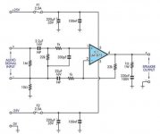
Reference: Brian Bell (Chipamp.com) LM1875 (schematic unknown)
Default configuration [components used in rabbitz build 2019]
R1 - not used (optional resistor to ground before C1) [not used]
R2 - 22k (input to ground resistor) [0.5W MF] 0,5 WATT R3 - 1k (gain resistor , gain = 1 + R4/R [0.5W MF] 0,5 WATT R4 - 22k (nfb resistor - on bottom of pcb) [0.5W MF] 0,5 WATT R5 - 2.7 2w (optional - zobel network) [2R7 2W MF] 2,7R - 3W R6 - jumper (optional resistor between input ground and output ground) [not used, linked]
C1 - 2.2µF (optional input capacitor) [1uF MMK] MMK version C2 - 22µF bipolar (optional) [Nichicon ES 22uF 25V] just 22µF C3 - 0.1µF (power supply decoupling) [ceramic X7R Vishay BC] XR7 Temp class C4 - 47µF (power supply decoupling) [Nichicon KZ 47uF 50V] 47µ Nichicon KZ C5 - 0.1µF (power supply decoupling) [ceramic X7R Vishay BC] XR7 Temp class C6 - 47µF (power supply decoupling) [Nichicon KZ 47uF 50V] 47µ Nichicon KZ C7 - 0.1µF (optional - zobel network) [MKT]
Note: 1K resistor after input cap not listed above but installed [0.5W MF]
https://www.diyaudio.com/forums/chip-amps/341675-ebay-mono-lm1875-kit-40.html#post6006059
Finally made a LM1875 amp
enjoy this amp
chris
here is my best parts list. the luxury housing and the bigger PSU is according to other members not relay needed.
rabbitz version is that( refered to Brain BEll)
Reference: Brian Bell (Chipamp.com) LM1875 (schematic unknown)
Default configuration [components used in rabbitz build 2019]
R1 - not used (optional resistor to ground before C1) [not used]
R2 - 22k (input to ground resistor) [0.5W MF] 0,5 WATT R3 - 1k (gain resistor , gain = 1 + R4/R [0.5W MF] 0,5 WATT R4 - 22k (nfb resistor - on bottom of pcb) [0.5W MF] 0,5 WATT R5 - 2.7 2w (optional - zobel network) [2R7 2W MF] 2,7R - 3W R6 - jumper (optional resistor between input ground and output ground) [not used, linked]
C1 - 2.2µF (optional input capacitor) [1uF MMK] MMK version C2 - 22µF bipolar (optional) [Nichicon ES 22uF 25V] just 22µF C3 - 0.1µF (power supply decoupling) [ceramic X7R Vishay BC] XR7 Temp class C4 - 47µF (power supply decoupling) [Nichicon KZ 47uF 50V] 47µ Nichicon KZ C5 - 0.1µF (power supply decoupling) [ceramic X7R Vishay BC] XR7 Temp class C6 - 47µF (power supply decoupling) [Nichicon KZ 47uF 50V] 47µ Nichicon KZ C7 - 0.1µF (optional - zobel network) [MKT]
Note: 1K resistor after input cap not listed above but installed [0.5W MF]
https://www.diyaudio.com/forums/chip-amps/341675-ebay-mono-lm1875-kit-40.html#post6006059
Finally made a LM1875 amp
enjoy this amp
chris
Attachments
Does anyone have a suitable BOM / shopping cart for mouser/digikey?l etc?
I was overwhelmed by the options then discovered not all components are available in Australia.
It's easiest to stick with the values in the original SC article as that's what I mostly did on my final build. The only change I made was the zobel 2R7/100nF, 220pF in lieu of 330pF and a 1uF MMK (MKT also OK) input cap. Make sure you use monolithic X7R for the 100nF by-pass caps.
You should be able to get most parts from Altronics and better power supply caps from RS Components if desired. Digikey is also good if you are ordering other components as well to make up the A$60 free shipping.
If you are having difficulty in sourcing I can send you 2 Nichicon ES 22uF 25V and 4 Nichicon or Panasonic 220uF.
Attachments

Hi rabbitz
thank you for your additionally inputs.
if you need ceramic isolation between the power chips. here i got some for my class A. watch out they are available with or without holes:
10pcs aluminium nitride ceramic substrate thermal conductive insulating ceramic TO 220/247/264/3P/3 aluminium nitride|Air Conditioner Parts| - AliExpress
chris
Hello guys, I'm thinking of using the LM1875 for my first DIY build. I'd like to use this with 84-85db 8ohm small desktop speakers.
Would this chip be OK with this kind of load at low-normal listening levels?
Assuming yes, it seems that the majority of the total build cost is the chassis and power supply, specifically the toroidal transformer.
Could you tell me what I would need there? I'm unclear if I need 1 transformer per channel or if I can run both channels off a single trafo?
On transformers, can anyone run me through the load requirements for a stereo amp to determine the secondary voltages and VA needed from the trafo?
Thanks!
The LM1875 would work fine with those speakers in a small to medium room at normal levels.
One transformer is ample and would suggest 15V-0-15V 80VA to 120VA. This will give around ±21-22VDC after rectification. You can use 18V-0-18V (±25-26VDC rails) but gets close to the limit of the chip especially with lower impedance speakers and the chip gets hotter with the higher rails. 4700uF caps per rail would be enough.
For some guidance on the LM1875, have a look at Rod Elliott's Project 72 as it gives some insight into the power supply.
Single Chip 25W Amplifier (Project 72)
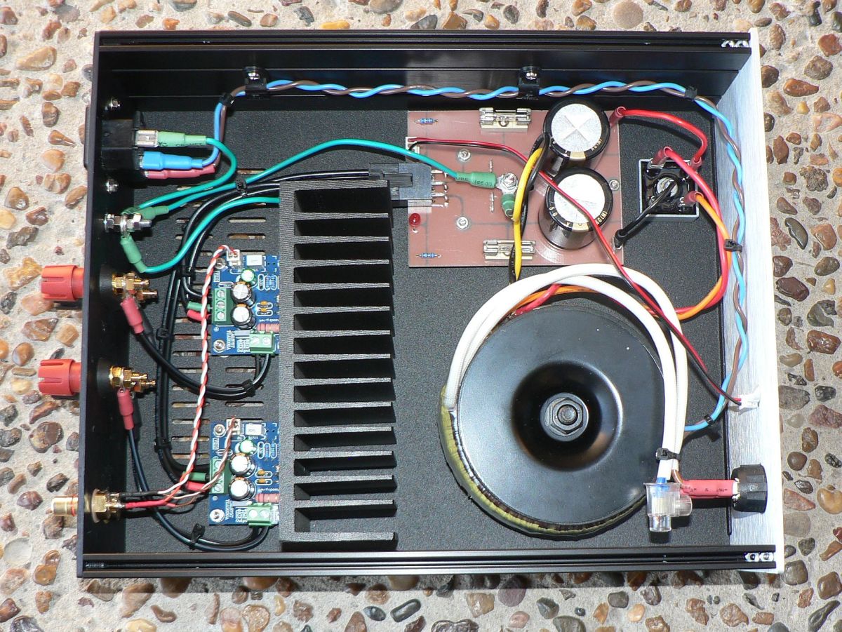
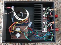
I've added a pic for reference showing a power supply with a single transformer in the build.
One transformer is ample and would suggest 15V-0-15V 80VA to 120VA. This will give around ±21-22VDC after rectification. You can use 18V-0-18V (±25-26VDC rails) but gets close to the limit of the chip especially with lower impedance speakers and the chip gets hotter with the higher rails. 4700uF caps per rail would be enough.
For some guidance on the LM1875, have a look at Rod Elliott's Project 72 as it gives some insight into the power supply.
Single Chip 25W Amplifier (Project 72)
I've added a pic for reference showing a power supply with a single transformer in the build.
Thanks a lot, rabbitz! The photo explains tons for me! So, this is great news it is possible to run 2 chips with 1 trafo and 1 rectifier, where you split the DC output to each LM1875 with that black cable. How did you do that, btw? Do you use a 6 conductor cable or special connector?
Regarding trafos, I have found Antek which seems much cheaper than anything else. They offer 100VA and then 200VA; nothing in between. Excluding cost and size, is 100VA less desirable than 200VA at all?
Regarding trafos, I have found Antek which seems much cheaper than anything else. They offer 100VA and then 200VA; nothing in between. Excluding cost and size, is 100VA less desirable than 200VA at all?
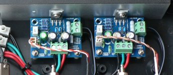
You have 2 DC outputs from each rail and PS ground. So you end up with Transformer > Bridge Recifier > Capacitors > 2 wires from each +ve, -ve and power ground. If you look at the Pic in post #847 there's a Molex with 6 leads and I've added a pic of a LM3875 where you can see it easier with different coloured wires. Red +ve, black -ve, green ground.
!00VA is fine and 200VA would be overkill.
!00VA is fine and 200VA would be overkill.
Attachments
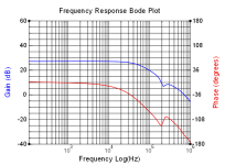
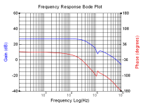
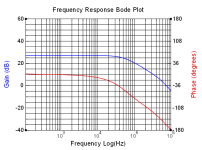
I've just made a quick set of frequency gain-phase response tests out to 1MHz on an ebay LM1875 kit with fake IC. I was interested in seeing the HF response to load change (no load, 8R, 16R, 32R) and to load capacitance (47nF, 100nF, 680nF). The hope was that the stock amp would be unconditionally stable, and it appears to be so. Testing was with just a +/-15V regulated rail supply, and only for 1W nominal output.
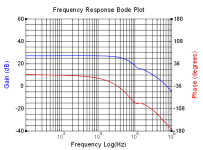
The mid-band gain is about +27dB, as anticipated. Out at 1MHz, the gain falls off to about -5dB (+/- about 1 to 2dB) for all load combinations, and phase has also similarly fallen to around 180deg.
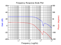
Of interest is a minor resonance related to capacitance loading, which occurs near 200kHz for 680nF, and increasing to 550kHz for 100nF, and similar for higher resistance loading.
I have previously used some small inductance to make certain valve amps unconditionally stable, so I included a simple emi axial leaded 6mm ferrite tube (circa 0.55uH, and mainly inductive from 20kHz to 600kHz) in series with any loading combination to see its effect. Adding the axial ferrite part had no noticeable affect except for when there was capacitance loading, where it suppressed the minor resonance and lowered its frequency a bit.
I had checked the frequency and distortion response using REW and an EMU0404, and that was consistent with datasheet and other testing I'd seen. The above testing to 1MHz was done with a Picoscope 4224A and FRA4 software.
I'll hopefully get some real LM1875's in sometime to compare, although my use for the amp is just for general instrumentation purposes. And I may get keen and test for clipping on-set response, but I'd likely use a burst of a small number of signal cycles to avoid any die heating effects.
The mid-band gain is about +27dB, as anticipated. Out at 1MHz, the gain falls off to about -5dB (+/- about 1 to 2dB) for all load combinations, and phase has also similarly fallen to around 180deg.
Of interest is a minor resonance related to capacitance loading, which occurs near 200kHz for 680nF, and increasing to 550kHz for 100nF, and similar for higher resistance loading.
I have previously used some small inductance to make certain valve amps unconditionally stable, so I included a simple emi axial leaded 6mm ferrite tube (circa 0.55uH, and mainly inductive from 20kHz to 600kHz) in series with any loading combination to see its effect. Adding the axial ferrite part had no noticeable affect except for when there was capacitance loading, where it suppressed the minor resonance and lowered its frequency a bit.
I had checked the frequency and distortion response using REW and an EMU0404, and that was consistent with datasheet and other testing I'd seen. The above testing to 1MHz was done with a Picoscope 4224A and FRA4 software.
I'll hopefully get some real LM1875's in sometime to compare, although my use for the amp is just for general instrumentation purposes. And I may get keen and test for clipping on-set response, but I'd likely use a burst of a small number of signal cycles to avoid any die heating effects.
Attachments

Wow ! all that work ....Just to 'save' the few $ a Genuine chip costs.
Astounds Me as to what some Zero in on as Important.
Astounds Me as to what some Zero in on as Important.
"Astounds Me as to what some Zero in on as Important.".
Bare, please note that I had just got a cheap ebay kit with the clone LM1875. I will use that amp as part of instrumentation for some projects, so wanted to confirm it was stable and with no unexpected performance. I have the benefit of being able to make very quick and easy frequency sweeps, so that "work" took less time than constructing and confirming nominal operation of the kit.
Btw, this is a diy forum, so if you don't find something important to yourself then perhaps don't find it important to respond to such a thread.
This simply supports my stand that the Chinese are quite capable of making good chips, which are very good in repair and new builds.
The big difference is price, the Chinese D1875 from CRC-Micro is about 10 cents landed in India, including duties and freight, to the importer, who has to take at least a carton of 50,000 units, or about $5,000.
The TI LM1875 costs about $3.20 from the likes of Mouser here, so buying 50k means an outlay of $160,000....or about $155,000 extra.
There are also chips which have other marks, and some are outright fake, with ST markings on TDA2030/50 chips.
I emphasize that I have no connection with any entity mentioned here.
The single chip mono kits sell for about 60 cents, wholesale.
In a market where a few cents can lose the order, it is not feasible to sell the finished goods at such a high price.
A photo of the chip will be appreciated.
I was under the impression that the fake ICs have distortion at high power (transient peaks?) and fail at high power. Or they fail in the long run of repeated use. I hope someone tests these.
Thanks and regards.
Thanks and regards.
There are threads on the cloned/faked IC's that show the internal die size differences with TI's original. It makes sense to me that die size and thermals would be a way to make a much cheaper clone device, whilst keeping the same base circuit. As such, I'm sure that incurs degraded performance for signal and operating voltage levels towards the maximum end of ratings. It's up to the user as to whether they bought the kit to operate right up to the original datasheet limits, or are happy to derate operation to well below those limits (that is my situation). The cloned devices are very easy to identify.
There are 'equivalent' and 'fake' ICs in the market, the 'equivalent' ones have the real maker's mark on them.
I agree, the 1875 can be run at +/- 25V into 4/8 ohms for 20W, and +/- 30V for 30W into 8 ohms, that needs a big supply and big heat sink.
The local amps I have seen use +/- 18V at most, with the cloned chips, and that is enough power for home use.
The real chips will also have problems if you run them at the limit with poor heat sink and small reservoir capacitors.
If you run at about 80% of the ratings, not much problem, and reliable.
Some amp builders use the cloned 2030, 2050 and 1875 interchangeably, so about +/- 10 V is found in those amps, 12-0-12 transformer and bridge rectifier is used, 2200 or 3300uF capacitor as reservoir.
Those are quite reliable, there is no thermal shut down or short circuit protection on the clones.
One more thing, the tests above in Post#851 are out into 100s of kHz, well out of audible range.
In the audio range, there is not much issue with sound quality in comparison to the real LM1875 chips.
In the audio range, there is not much issue with sound quality in comparison to the real LM1875 chips.
Yes those plots are out to 1Mhz, which is luckily 'just' wide enough to show the closed loop response characteristic out to a region indicating 0-deg phase and 0dB gain margins for stability assessment. Squarewave testing with different loads could confirm no resonance/feedback issues beyond 1MHz that could be 'hidden' by frequency sweep testing only to 1MHz.
I could identify only one youtube video that did squarewave testing, with resistive and capacitor only testing, but not no-load. The capacitor only loading showed up damped resonance at about 220kHz, which aligns with the gain phase plots in post #851. That video didn't identify the scope model, although plots with 5us timebase indicate a bandwidth beyond 10MHz.
I could identify only one youtube video that did squarewave testing, with resistive and capacitor only testing, but not no-load. The capacitor only loading showed up damped resonance at about 220kHz, which aligns with the gain phase plots in post #851. That video didn't identify the scope model, although plots with 5us timebase indicate a bandwidth beyond 10MHz.
- Home
- Amplifiers
- Chip Amps
- eBay mono LM1875 kit