Hi turbo, thanks again for a comprehensive answer.
I'm sorry if that wasnt clear but I know my 60hz hum is caused by the poor layout that came as a result of finding a spot for the protection board. It sits millimeters away from the transformer... for starters. It also required me to route speaker wires near 120v lines. And now you're telling me it might be also causing a ground loop.
But I need the protection board to avoid the on/off pop, I will need to find a proper layout in the final enclosure, and most likely plan for an independent supply.This however will probably wait for a bit, as I need to find/order and or build the final enclosure.
The hdmi adapter noise remains a mystery to me...
All in all I've learned a bunch, and it already sounds like an amp.
Chris, what did you want to pump up?
"Get rid of the protection board" was to solve any hum problem first, so for example the HDMI. When anything runs unconditional silent, you can add the protection and see how you solve it´s problem.
Take care to connect ground only once to the protection board. often you are tempted to connect ground 3 times, one with each speaker wire, one with supply power.
You can build amps on a very small area, but you have to take care of any single wire. Sometimes it is impossible to put components as close together as you like. The last help might be small, thin sheet metal plates (steel!) to separate them.
The way to do it, in any case is to start with the fewest components possible, test, solve hum problems, then add the next part. Don´t fit everything together and expect it to be silent.
pump up..
I am just irritated that i think that the advise by Turbowatch that the earth should not be connected with the input signal GND - but this happened at the mono board?
at my mock up if haven´t an earth connection. small hiss at the speakers very near the tweeter. so no problem...sound is still fine.
chris
You should not run two ground wires to the input RCA socket, but only one, which is connected to both socket´s ground. Like a T. The signal wire should be well screened, but only grounded at one side. This prevents the screen from producing hum, which is a common problem with this wire. If you use the screen as earth, dependent on how you route it, it will pick up more or less dirt.
This makes you ask where to put the signal ground at the amp PCB´s.
It depends on your ground concept. The first try may be a central ground, often at the power supply.
There is no universal solution, as in the end the amp which is silent in any case of connection has the right concept. Don´t produce ground loops and make your self understand where the current comes from and ends. With single ended amps the ground, which is speaker negative, ends at the power supply, not the amp PCB. So in most cases it is best to connect it there, even as the PCB has Speaker negative too.
A nice way to find the right concept, if you run into hum problems, is to use crocodile clips with short wires for the ground connections. You can try all kinds of options in a few minutes.
I´m no friend of a hard ground to earth connection which you need with a metal case. There are many concepts to lift the ground a bit. Like resistors, caps and diode´s.
For example if you have a pre-amp and power amps at each speaker Like bi-amping), you may have quite some trouble to keep hum away.
Add an active x-over and a sub woofer amp, connected to mains power on different wall outlet´s. Still silent? Lucky you!
Last edited:
Again, for the protection board:
First it needs power and ground to run (like + and - voltage).
Then it needs power amp output ground to look for DC on the speaker line, which means speaker + and -.
There you see the problem: You instantly get some kind of ground loop. You have to get around this!
If you use one power supply for two amps, you have to ground the protection board only once, at the PS.
If you have a dual mono build with two PS´s, you have to use two protection boards. A good idea anyway, as you have two relay contacts in parallel.
I'm late to this thread but a quick comment, in general you want to mount heat sinks with the fins running vertically instead of horizontally so the convection air rises naturally.
tommost
tommost
Hi everyone, back to the Ebay Mono boards, if you guys don't mind 😉
I finally played some music with my build last night (The enclosure is 'minimal' to say the least).
2xEbay Boards with the components Rabbitz suggested (all legit parts from Digikey). A 2x18v 100VA transformer and 20000uf per rail supply. Oddly enough the transfo gives me +- 27VDC once rectified (it seems wound for a bit over 18v). Now Im 6v under the 60V max supply for the chip, so I assume Im ok here.
The dc offset was 1.7 and 2.2mV, that's acceptable right?
Now I get a kinda annoying thump sound when I power up or down the amp, I remember reading that some experienced that with legit LM1875s, did anyone find a fix for that?
Aside from that well, I couldn't stop listening to it, I was so excited to have my first DIY amplifier working.
Thanks,
-Joey
Again, for the protection board:
If you use one power supply for two amps, you have to ground the protection board only once, at the PS.
I tested that the mounting holes pads on the protection board are floating. So the only ground loop problem I see then is the board might be linking signal ground with PS ground. I don't see how I can solve that if it's part of the board. If I don't connect the audio minus (speaker -) to the relays the DC protection will not work, wouldn't it?
I tried moving the transfo away from the protection board, but that doesnt change anything. So my suspects are :
- Speaker wire routing too close to the 120v mains to reach the protection board.
- Protection board ground loop
- Mono boards that strap the signal to ps ground without a resistor.
Ive been strapped for time lately so I didnt work much on this, thanks all for taking your precious time to post here.
-Joey
Yes, you realized the problem. You have to try out what works for you. There should be no need for a ground connection to the amp board, if it already is connected to the power supply ground.
If you need to connect amp 1, amp 2 and power supply ground to the protection board, I promise a very loud hum.
So connect all ground points of the protection board together and then to power supply ground. Should work. If not, try alternatives until everything is silent.
If hum is picked up by a wire, you can modulate it when you move it only a little. If not,
it is no induced hum, but a loop.
Induced hum is much less of a problem than many might think. Have a look at other amps (commercial, too), how narrow anything is, while the amps are perfectly quiet.
Do not think hum can not be avoided with your components, any amp can be hum free. You are just doing something wrong. Try to accept this and look for a solution.
The most easy way it to make a plan of all ground connections. Think of heat sinks too, they should be grounded and any metal part screwed to them needs an isolation pad. Otherwise they will burn off!
PS maybe post a picture of your installation? If it is neat and clean, chances it will work are much better than using the last shoe string you can find to make it "work somehow" for a test. Do a clean install even for a test.
Last edited:
Hi Turbo,
I have no problem accepting im doing something wrong haha.
Here's a few pictures,
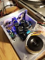
Pic 1 : So the original plan without the protection board made it quite neat IMO, short low signal runs, short speaker runs, audio boards as far away as possible from the transformer, etc.
Pic 2 : So you can see how adding the protection board messed the layout/wiring. Now you have the speaker wires from the left board looping all around and going quite newar the 120v.
Signal shields : The screen is linked to the negative signal at the RCA only, im using shielded microphone cable.
Edit: Btw, the hum is not loud, but its there.
I have no problem accepting im doing something wrong haha.
Here's a few pictures,
Pic 1 : So the original plan without the protection board made it quite neat IMO, short low signal runs, short speaker runs, audio boards as far away as possible from the transformer, etc.
Pic 2 : So you can see how adding the protection board messed the layout/wiring. Now you have the speaker wires from the left board looping all around and going quite newar the 120v.
Signal shields : The screen is linked to the negative signal at the RCA only, im using shielded microphone cable.
Edit: Btw, the hum is not loud, but its there.
Attachments
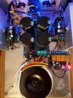
The protection board you have is for bridged amps. I think that might be a problem.
It is made to work independent of ground, the relay contacts are separate. So you have speaker + and- , positive supply and ground. I can not predict how this works out with your installation. As it costs only 5$, maybe get a protection board not usable with bridged amps?
The other problem, you have power grid earth connected to your metal case. While this is good for safety, it will give you problems with hum.
I ignore safety ground during build up and connect it as the last thing, only when the amp is 100% hum free. This way I can solve this problem last.
Nothing is worse than multiple causes for the same problem.
I write "hum free", not noise free, as some high frequency hiss is usually in the tweeter and some induced noise, like mobile phones and DECT stuff can not always be kept out. As long as it is an open installation such noises is no problem.
There is one thing I would instantly remove: You use wire that has two lines in parallel. Absolut no go inside an amp! Even as you can build silent amps with it, there might arise problems you do not see or hear and suddenly lead to a "burning chip" from oscillation.
The best you can do is to get some solid core wire for electric installation, the stuff you find a mile in every house. Best is the 5-core, so you get the different colors. Remove the outer insulation and use a drill to make nice twists with 2 lines for speaker and 3 for power connection.
This stuff is a bit tough to bend and it might take some time to make a force free installation to the contacts. Do not let it run in parallel with other wires, a 90° crossing is OK.
You can make the same from soft wire, but it might be harder to get and much more expensive.
Your over all installation should be OK, even as it is a bit on the narrow side. The bulky power connector might be worse than a fixed wire, even as this does not look professional.
PS see next post for example of twisted wire
Last edited:
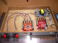
This was just for a quick test. Such an installation takes not even 10 minutes more than just connecting anything on the table, but prevents any accident.
For permanent use of a D-amp SMPS combo I use closed metal cases, as EMF radiation is punished in my part of the world.
I have no clue where the wooden tablet comes from. Maybe 50 years or older...
The second amp PCB that is not conneced is the same article, just without heat sink/ fan.
For permanent use of a D-amp SMPS combo I use closed metal cases, as EMF radiation is punished in my part of the world.
I have no clue where the wooden tablet comes from. Maybe 50 years or older...
The second amp PCB that is not conneced is the same article, just without heat sink/ fan.
Last edited:
Hi
i want to change on the mono boards the chip 1875 to UTC2050. long story short i got a bad connection"in the board" dont ask me why. i know that more then once soldering the solder dots get lost but this is new for me. if i switched on the V+ or the V- alone everything is fine - but both are shorting!!
ok strange pcb material...
ok. my idea was to check the chip alone or in a separate board where i can just change the chip easily. a DIL socket is not working, the breadboards are to small.
yes i can check directly at the pins for the first check..but without changing the feddback resistor...etc..
pin 2 GND
pin 3 V-
pin 5 V+
what is your idea?
chris
Hi Chris,
I managed to make a small test-board using an IC-socket with flat contacts which I cut in pieces. I will post a photo tomorrow.
I cannot test with high currents but certainly if an IC (LM1875/"fake"/TDA2050) is functional or not. I have checked all my items.
The most simple test without such a test-board is to measure the impedance from the output pin and to the two supply pins, and between the two supply pins.
Chris,
If i understand your question correctly, a socalled ZIF socket might be what you're looking for.
A 14 pin version can also be easily modified to fit a "5 pin" lm1875/tda2050 etc.
Look here: ZIF Socket modification to test eg TDA2050/LM1875
Fred
If i understand your question correctly, a socalled ZIF socket might be what you're looking for.
A 14 pin version can also be easily modified to fit a "5 pin" lm1875/tda2050 etc.
Look here: ZIF Socket modification to test eg TDA2050/LM1875
Fred
Last edited:
Hi Chris,
I managed to make a small test-board using an IC-socket with flat contacts which I cut in pieces. I will post a photo tomorrow.
I cannot test with high currents but certainly if an IC (LM1875/"fake"/TDA2050) is functional or not. I have checked all my items.
The most simple test without such a test-board is to measure the impedance from the output pin and to the two supply pins, and between the two supply pins.
Hi FF
i did this partly to see if my chip is dead then i found this problem with the "internal short"..
i checked 4x UTC 2050 and 3 LM1875 origin with my LCR-Meter Peak tech 2170- setting to RS setting and 1khz.
the black probe is on the pin3 - heat sink of the chip- with the red probe i go to different pins
UTC2050
pin 3-5 about 1k3R pin 3-4 1k3R
pin 3-2 about 103kR pin 3-1 103kR
LM1875
pin 3-5 about 1k1R pin 3-4 1k1R
pin 3-2 about 1k2R pin 3-1 1,k2R
at both chips the measurments between pin 1-2 was jumping around from 104k up to some 5 or 7Megohms
chris
Hi Chris,
I managed to make a small test-board using an IC-socket with flat contacts which I cut in pieces. I will post a photo tomorrow.
I cannot test with high currents but certainly if an IC (LM1875/"fake"/TDA2050) is functional or not. I have checked all my items.
The most simple test without such a test-board is to measure the impedance from the output pin and to the two supply pins, and between the two supply pins.
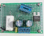
Hi Chris,
A photo of my LM1875/TDA2050 test board. More components on the rear side.
The blue IC socket standing on the board is just to show you what kind of socket I used before cutting it in two pieces. You can see that I bend the LM1875 pins a bit outwards to fit in the socket.
Attachments
Hi FF
i did this partly to see if my chip is dead then i found this problem with the "internal short"..
i checked 4x UTC 2050 and 3 LM1875 origin with my LCR-Meter Peak tech 2170- setting to RS setting and 1khz.
the black probe is on the pin3 - heat sink of the chip- with the red probe i go to different pins
UTC2050
pin 3-5 about 1k3R pin 3-4 1k3R
pin 3-2 about 103kR pin 3-1 103kR
LM1875
pin 3-5 about 1k1R pin 3-4 1k1R
pin 3-2 about 1k2R pin 3-1 1,k2R
at both chips the measurments between pin 1-2 was jumping around from 104k up to some 5 or 7Megohms
chris
I will check mine..........
- Home
- Amplifiers
- Chip Amps
- eBay mono LM1875 kit