Ebay 300B schematic
This is the circuit with the values that are on the PCB. Your trace out is missing a cathode bypass cap on the 15k resistor.
Board Build:
A couple component values were changed due to different parts being provided vs what was on the silkscreen:
300B Grid resistor which changed from 220K to 205K
300B Cathode Resistor bypass cap changed from 470uF to 220uF
Filter cap for the first gain stage changed from 10uF to 22uF
I was short one 22uF 450V cap and had to use one I had on hand that was a 22uF 400V Nichikon KMX
I also had one Rubycon SV570 82uF BN A(2) capacitor and an LED left over.
Changes I made:
I did not place the 22pf cap on the input
I changed the input grid resistor from 100K to 1 Meg, and added a 100K pot on the input
I changed the 300B cathode resistors from 2 X 2K in parallel to 2 X 2.4K in parallel
Changes are in blue on the attached schematic.
6A3sUMMER,
I was lazy on the 300B and did not calculate the stage gain. I should have. It puts the overall amplifier down to roughly 2.5 vs previously shown 3.07, even worse from a drive standpoijnt.
This is the circuit with the values that are on the PCB. Your trace out is missing a cathode bypass cap on the 15k resistor.
Attachments
Aha thank you for catching that.
The cap would explain the greater gain I am seeing compared to the calculated gain without the bypass cap.
I just verified the 22pf cap which you show incorrectly. It goes from Pin 1 of the tube to ground. I left it out.
The cap would explain the greater gain I am seeing compared to the calculated gain without the bypass cap.
I just verified the 22pf cap which you show incorrectly. It goes from Pin 1 of the tube to ground. I left it out.
With the schematic in post 65 leaving off the cathode cap on the second stage we have:
Transformer turns ratio is SQRT (3000/8) 19.36
amplifier gain is 11.9 * 1.28 * 3.19 / 19.36 = 2.51
For 8 W out 8Vrms is required to an 8 ohm load, so input drive is 8/2.51 = 3.18Vrms.
First stage amplification:
3.18Vrms * 11.9 = 37Vrms = 107Vp-p or 53.5Vp
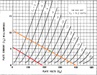
Looking at the red loadline we see from the bias point (blue star) to the Ec=0 curve is only about 30V, and this is probably what Stephe was talking about in post 94, since it will result in clipping well before full output.
Since the amplifier actually has a bypass cap on the second stage cathode, it behaves differently.
Actual Gain Structure:
First gain stage the same as previous:
AV1 = 11.9
Second stage V2b 6SN7 Bypassed
AV =(Mu * RP) / (Rp-+ Ra)
= (20 * 33K) / (33K + 6700)
= 660K / 39700
= 16.6
300B is the same as previously calculated:
= 3.10
Transformer turns ratio is SQRT (3000/8) 19.36
amplifier gain is 11.9 * 16.6 * 3.19 / 19.36 = 32.55 vs 2.51 previously calculated.
For 8W we only need:
8Vrms / 32.55 so drive is 0.245Vrms
with a stage gain of 11.9 for the first stage, it’s output will be 2.92Vrms or 8.27Vp-p which the gain stage can accommodate without clipping.
This explains why I did not hear the problem Stephe was talking about.
This amp starts clipping when the driver voltage approaches the Vg=0 condition to the 300B.
Transformer turns ratio is SQRT (3000/8) 19.36
amplifier gain is 11.9 * 1.28 * 3.19 / 19.36 = 2.51
For 8 W out 8Vrms is required to an 8 ohm load, so input drive is 8/2.51 = 3.18Vrms.
First stage amplification:
3.18Vrms * 11.9 = 37Vrms = 107Vp-p or 53.5Vp
Looking at the red loadline we see from the bias point (blue star) to the Ec=0 curve is only about 30V, and this is probably what Stephe was talking about in post 94, since it will result in clipping well before full output.
Since the amplifier actually has a bypass cap on the second stage cathode, it behaves differently.
Actual Gain Structure:
First gain stage the same as previous:
AV1 = 11.9
Second stage V2b 6SN7 Bypassed
AV =(Mu * RP) / (Rp-+ Ra)
= (20 * 33K) / (33K + 6700)
= 660K / 39700
= 16.6
300B is the same as previously calculated:
= 3.10
Transformer turns ratio is SQRT (3000/8) 19.36
amplifier gain is 11.9 * 16.6 * 3.19 / 19.36 = 32.55 vs 2.51 previously calculated.
For 8W we only need:
8Vrms / 32.55 so drive is 0.245Vrms
with a stage gain of 11.9 for the first stage, it’s output will be 2.92Vrms or 8.27Vp-p which the gain stage can accommodate without clipping.
This explains why I did not hear the problem Stephe was talking about.
This amp starts clipping when the driver voltage approaches the Vg=0 condition to the 300B.
Attachments
Last edited:
Yes, I confirmed the driver stage was hitting 0V grid voltage when clipping started and distortion went up. The input stage was no where near clipping. I continued increasing the input drive until the input tube started clipping, It took a much larger input signal to push the input tube to clipping.
Hi, I'm interested in building this kit
I don't have the knowledge of all of you guys but I like to learn new things
I wonder if you can help me choosing the correct parts to building it
I already locate the board
300B Single ended Class A Stereo Amplifier Tube Amplifier Board Preamplifier PCB DIY Kit|Amplifier| - AliExpress
For the power transformer
AS-3T325 - 300VA 325V Tube Transformer - AnTek Products Corp
for the choke
LK-8H100 Toroidal Power Choke - AnTek Products Corp
For output transformers
MS-30W25 30W Single Ended Output Transformer - AnTek Products Corp
what do you think?
MS-30W25 is 2.5K primary
MS-30W50 is 5.0k primary
Nice prices, but performance is unknown:
Both of them show no low frequency roll off at 10Hz.
That means they tested them by using a 50 Ohm signal generator (unfair test).
Your amplifier will use a 300B to drive the primary, it will not use a 50 Ohm generator.
A 300B plate resistance, rp, of 700 Ohms will not give a flat low frequency response that the data sheet shows.
There will be low frequency roll off, but when will it start, you can not know from the manufacturers data sheet, they do not list the primary inductance.
Will the transformer be -3dB at 70Hz, 40Hz, 30Hz . . . unknown.
We do know the high frequency response of those models.
2.5k is -2.5dB at 20kHz and -1dB at 12kHz
5.0k is -2.5dB at 10kHz and -1dB at 4.5kHz.
$89 sounds economic, but will the output transformer sound good? Maybe not.
Last edited:
Power Transformer for 300B kit
For the power transformer you will need 1 more filament supply. You can pad down one of the 6 volts with resistors and use on the rectifier filament, and I would source a pair of 5v 2 amp transformer for the 300B's. Or you could pad down the 6.3's and use on the 300B's and buy 1 5v for the rectifier but get a 3 amp so you can use 5U4 tube.
I would also shop for a known quality output transformer.
Hi, I'm interested in building this kit
I don't have the knowledge of all of you guys but I like to learn new things
I wonder if you can help me choosing the correct parts to building it
I already locate the board
300B Single ended Class A Stereo Amplifier Tube Amplifier Board Preamplifier PCB DIY Kit|Amplifier| - AliExpress
For the power transformer
AS-3T325 - 300VA 325V Tube Transformer - AnTek Products Corp
for the choke
LK-8H100 Toroidal Power Choke - AnTek Products Corp
For output transformers
MS-30W25 30W Single Ended Output Transformer - AnTek Products Corp
what do you think?
For the power transformer you will need 1 more filament supply. You can pad down one of the 6 volts with resistors and use on the rectifier filament, and I would source a pair of 5v 2 amp transformer for the 300B's. Or you could pad down the 6.3's and use on the 300B's and buy 1 5v for the rectifier but get a 3 amp so you can use 5U4 tube.
I would also shop for a known quality output transformer.
That AliExpress sale shows two completely different circuit boards.
The board I have is Black, not blue, and is marked:
300B (J) V1.1
and:
2578AY-300B
Regrettably, there are many boards out there and the websites selling them seem to mix photos and schematics in a random fashion.
The board I have is Black, not blue, and is marked:
300B (J) V1.1
and:
2578AY-300B
Regrettably, there are many boards out there and the websites selling them seem to mix photos and schematics in a random fashion.
One caution about this kit:
It contains a PCB and a bag of components.
In my case all of the components do not match the silkscreen markings on the PCB. Most did.
There are no instructions.
One must make educated guess as to where the parts go. Most parts are obvious.
However, the kit may have extraneous components and be short of required components, and one has to be able to figure out what is inconsistent and be willing to either (1) contact the supplier for missing components, or (2) source the missing parts your self.
If you buy a kit, ask us questions. I and many others are willing to help, but you have to ask when you are not 100% certain.
The only stupid question is the one that is not asked.
Thanks all for your help, you are right, the kits are different
I will buy the black one on Ebay
Could you pease recommend me a good quality output transformer?
One of my projects was a EAR834 MM RIAA Tube Phono Amplifier and investigating for a step up transformer I came up with Lundahl as one trust brand but they are pricey.
The Antek products are really good but I have experience only on power supply, I just thought the brand was known in the tube world.
They use toroid transformers which have advantages and disadvantages. For power they are fine. I have not tried their OPTs.
Where are you located? This will have a large bearing with respect to shipping and other charges over the list price of the transformers.
Where are you located? This will have a large bearing with respect to shipping and other charges over the list price of the transformers.
I'm in Guatemala, But I have a shipping service located in Miami, so all the things that I order I send it to the Miami address and they after that send all the packages to Guatemala by air.
The One Electron UBT-3 transformers I am using do not show as being available through Antique Electronics Supply any more. I don't know it One Electron still makes them or not.
I think that leaves Hammond and Edcor neither of which I have used.
Hopefully someone who has will speak up.
I think that leaves Hammond and Edcor neither of which I have used.
Hopefully someone who has will speak up.
Hi, I'm interested in building this kit
I don't have the knowledge of all of you guys but I like to learn new things
I wonder if you can help me choosing the correct parts to building it
I already locate the board
300B Single ended Class A Stereo Amplifier Tube Amplifier Board Preamplifier PCB DIY Kit|Amplifier| - AliExpress
Hi,
I went or this KIT.
It should arrive in a week or two.
I changed the transformer to an Edcor XPWR002 in order to get the B+ above 350V. I ended up around 410 V for B+, 363 Vak, Ik 59mA, dissipation around 21W.
After running for a few minutes I saw smoke and shut it down. the left side cathode resistors smoked.
I am running PSVANE HIFI 300Bs (Black Box, white base, silver print). The datasheet shows operation to Vak=450V.
I have replaced the cathode resistors and inspected the board and see no other damage.
I plan to bring it up slowly with a variac and let it stabilize at Vak 250 before increasing B+.
Before I do I would be open to other suggestions on bringing it up, and opinions of what caused the run-away.
😀 just encountered smoke and loud spark of resistor too on preamp, ficking scary 😀 When saw slowly smoke came out, turned off and checked but didn't see where, then kept trying for few more times until it popped, was standing 3ft away with on/off switch on my finger ready for action. I got nervous and didn't look again for a day to have confident again. 🙂
Maybe use 20w resistor at cathode and 450v cap.
Maybe use 20w resistor at cathode and 450v cap.
There are two 2400 Ohm 5W resistors in parallel with an additional pair of 15 ohm resistors to the filaments. the 2400 ohm resistors are supposed to be 5W each, that gives me a 4.25W dissipation on 10W rated resistors. That shouldn't be an issue. I can test a resistor to see how much it can take before it smokes. I have 50 of them, well now 44 left.
Another causes:
- oscillation of the previous stages;
- bad coupling capacitor;
- bad grid leak resistor.
- oscillation of the previous stages;
- bad coupling capacitor;
- bad grid leak resistor.
Your cathode resistors - a pair of 2.4k in parallel - are dissipating 4.2w. What's their wattage rating?I changed the transformer to an Edcor XPWR002 in order to get the B+ above 350V. I ended up around 410 V for B+, 363 Vak, Ik 59mA, dissipation around 21W.
After running for a few minutes I saw smoke and shut it down. the left side cathode resistors smoked.
I am running PSVANE HIFI 300Bs (Black Box, white base, silver print). The datasheet shows operation to Vak=450V.
I have replaced the cathode resistors and inspected the board and see no other damage.
I plan to bring it up slowly with a variac and let it stabilize at Vak 250 before increasing B+.
Before I do I would be open to other suggestions on bringing it up, and opinions of what caused the run-away.
Typically, you want to derate by at least a factor of 3, which would be 12.6w. I prefer to derate by 5x. The schematic shown earlier shows a 1k 20w.
Even if they are sized correctly they will get quite hot. Mounting them close to the board, as you seem to be doing, is asking for trouble, IMO.
- Home
- Amplifiers
- Tubes / Valves
- eBay 300B PC board kit