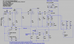
Based on my schematic, I have made the following calculations for the amplifier:
300B operating point calculations
Transformer supply:
FX-270 measured 661Vac no load, 330 per phase
330 * SQRT2 = 467V
Transformer secondary is 46 ohms per phase, presuming 80 ma per phase, 160ma total, IR drop is 4V
5U4 drop is 40V (at 225 mA per plate so conservative)
Choke 55 ohms at 160mA gives 8.8V drop
467 – 4 – 40 – 8.8 is approximately 414V at the B+ point.
Figure 5% drop for loading of other windings yields 393.5 V, so 390 may be achievable.
Gain structure:
V2a 6SN7
B+ 390V (First approximation based on Hammond FX-270 and line voltage of 130V)
Rk = 750R, Ra = 33K, Ri = 10MEG Grid input (no resistor), VA = 90V
Since VA = 90V a first approximation of Ia = 390-90 / (333K + 68K) = 7.35mA
Datashees shows at 90VA 10mA, Mu = 20, Ra = 6700, Gm = 3000
AV =(Mu * RP) / (Rp-+ Ra, + (Mu + 1)* Rk)
=(20 * 33K) / (333K + 6700 + (20 + 1) * 750
=660K / 55,450
AV1 = 11.9
V2b 6SN7
Ia = Vg/RK = 90 / 15K = 6mA
RK = 15K, Rp = 22K, Ri = 220K
AV =(Mu * RP) / (Rp-+ Ra, + (Mu + 1)* Rk)
= (20 * 22K) / (22K + 6700 + (20 + 1) * 15K
= 440,000 / 341700
AV2 = 1.28
300V Mu is about 3.9.
Transformer turns ratio is SQRT (3000/8) 19.36
amplifier gain is 11.9 * 1.28 * 3.9 / 19.36 = 3.068
For 8 W out 8Vrms is required to an 8 ohm load, so input drive is 8/3.068 = 2.61Vrms
My sources are a little shy of that so I don’t expect to drive the amp to full output with out mods.
So now to build it and see what it does.
Attachments
300B operating point
3K transformer
390V B+
Transformer resistance 286R
From the WE data sheet there are two bias points close
300V at -63V and 50ma (1260R)
and 350V at -74V and 60mA (1233R)
split the difference and get 325V at -68.5V 55mA
55mA transformer loss 15.7V
390V – 15.7V -68.5V = 305V so closer to 300V at 50mA
Use two 2400 Ohm resistors in parallel for 1200R gets me close.
Attachments
TheGimp,
'u' (mu), and 'stage gain' are not the same thing
300B u ~ 3.9
300B rp ~ 700 Ohms
With RL = 3000 Ohms . . .
Then 300B gain is u x (RL/(RL+rp))
3.9 x (3000/3700) = 3.16
Gain is 3.16. It is not 3.9.
20 x log (3.16/3.9) = 1.8 dB less stage gain versus u.
'u' (mu), and 'stage gain' are not the same thing
300B u ~ 3.9
300B rp ~ 700 Ohms
With RL = 3000 Ohms . . .
Then 300B gain is u x (RL/(RL+rp))
3.9 x (3000/3700) = 3.16
Gain is 3.16. It is not 3.9.
20 x log (3.16/3.9) = 1.8 dB less stage gain versus u.
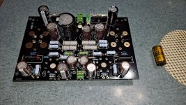
Board Build:
A couple component values were changed due to different parts being provided vs what was on the silkscreen:
300B Grid resistor which changed from 220K to 205K
300B Cathode Resistor bypass cap changed from 470uF to 220uF
Filter cap for the first gain stage changed from 10uF to 22uF
I was short one 22uF 450V cap and had to use one I had on hand that was a 22uF 400V Nichikon KMX
I also had one Rubycon SV570 82uF BN A(2) capacitor and an LED left over.
Changes I made:
I did not place the 22pf cap on the input
I changed the input grid resistor from 100K to 1 Meg, and added a 100K pot on the input
I changed the 300B cathode resistors from 2 X 2K in parallel to 2 X 2.4K in parallel
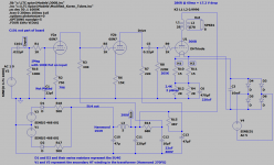
Changes are in blue on the attached schematic.
6A3sUMMER,
I was lazy on the 300B and did not calculate the stage gain. I should have. It puts the overall amplifier down to roughly 2.5 vs previously shown 3.07, even worse from a drive standpoijnt.
A couple component values were changed due to different parts being provided vs what was on the silkscreen:
300B Grid resistor which changed from 220K to 205K
300B Cathode Resistor bypass cap changed from 470uF to 220uF
Filter cap for the first gain stage changed from 10uF to 22uF
I was short one 22uF 450V cap and had to use one I had on hand that was a 22uF 400V Nichikon KMX
I also had one Rubycon SV570 82uF BN A(2) capacitor and an LED left over.
Changes I made:
I did not place the 22pf cap on the input
I changed the input grid resistor from 100K to 1 Meg, and added a 100K pot on the input
I changed the 300B cathode resistors from 2 X 2K in parallel to 2 X 2.4K in parallel
Changes are in blue on the attached schematic.
6A3sUMMER,
I was lazy on the 300B and did not calculate the stage gain. I should have. It puts the overall amplifier down to roughly 2.5 vs previously shown 3.07, even worse from a drive standpoijnt.
Attachments
Last edited:
I have to pick up some hardware from the hardware store tomorrow to mount the PCB to a section of plywood for prototyping.
Looking at the gain structure, it seems to me that it would be easy to change the 15K cathode resistor in the second gain stage to a 4.7K on top and a 10K on the bottom. Bypass the bottom 10K and the gain becomes determinant on the 4.7K upper Cathode/feedback resistor.
V2b 6SN7
Ia = Vg/RK = 90 / 14.7K = 6.122mA
RK = 14.7K, Rp = 22K, Ri = 220K
AV =(Mu * RP) / (Rp + Ra, + (Mu + 1)* Rk)
= (20 * 22K) / (22K + 6700 + (20 + 1) * 4.7K)
= 440,000 / 127400
AV2 = 3.45
That increase would put the overall gain structure to:
amplifier gain is 11.9 * 3.45 * 3.25 / 19.36 = 6.89
Drive requirement drops to 8Vrms / 6.89 = 1.16 Vrms
This should be pretty easy to drive.
I will have to look at LF roll-off due to the bypass cap. and figure it's value.
When calculating the output impedance of the cathode, RK' still remains:
Rk' = (Ra + ra)/ ( Mu + 1)
Rout = Rk'||Rk where Rk is only the un-bypassed portion of the cathode resistance? Correct?
So:
Rk' = (22K + 6700) / (20 + 1)
= 1.367K
Rout = (1.367K * 4.7K / (1.367K + 4.7K)
= 1059R
High Pass break-point due to Ck/Rk
F = 1/ (2 * Pi * Ck * Rout)
F * Ck = 1/ (2 * Pi * Rout)
Ck = 1/ (2 * Pi * Rout * F)
Choose 30Hz
Ck = 1 / (2 * Pi * Rout * 30)
Ck = 1 / ( 2 * 3.14159 * 1059 * 30)
Ck = 5uF
This doesn’t seem right as it ignores the 10K being bypassed, or is it ignored because the bypass capacitor has an Xc that is very low?
At 30Hz Xc is 1/(2 * Pi * F * C) = 1 / (2 * 3.14159 * 30 * 5e-6) = 1061 ohms.
Xc in parallel with R is 1061 || 10,000 = 959 ohms This seems significant.
Should this be added back into the equation for Rk’?
If I calculate Rout' with the 10K in parallel with Rout it does not make much difference:
Rout’ = (Rout * 10K) / (Rout + 10K)
= (1059 * 10,000) / (1059 + 10,000)
= 957.6
Ck = 1/ (2 * Pi * Rout * F)
Choose 30Hz
Ck = 1 / (2 * Pi * Rout * 30)
Ck = 1 / ( 2 * 3.14159 * 957.6 * 30)
Ck = 5.5 uF
Rout’ = (Rout * 10K) / (Rout + 10K)
= (1059 * 10,000) / (1059 + 10,000)
= 957.6
Ck = 1/ (2 * Pi * Rout * F)
Choose 30Hz
Ck = 1 / (2 * Pi * Rout * 30)
Ck = 1 / ( 2 * 3.14159 * 957.6 * 30)
Ck = 5.5 uF
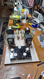
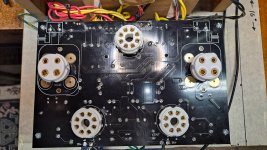
First pass layout for debugging.
I plan on using a 12" (30.48cm) wide X 16" (40.64cm) deep aluminum plate for the deck. I think I should rotate all transformers 90 degrees to give more room between the OPTs and output tubes.
Yes, one of the OPTs is cantered. Hand drill and I slipped holding it below the plywood.
Does anyone see anything wrong with my previous calculations in the last three posts?
Would I be better moving the OPTs to the rear and moving the power transformers forward. This would result in shorter power wiring and longer OPT wiring. OPT has less wires so it might make sense.
Magnetically, does it matter. I think not but am open to ideas.
Attachments
Last edited:
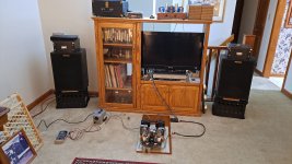
On my build, OPT are on the rear and the power transformer is completely outside of the amp, all the cables running through XLR connectors.
Preliminary power up shows the 5U4 is miss-marked on the silkscreen. I will have to disassemble the amp, remove the socket and re-install it.
Also the 300B filament voltage is too high, 5V at 120VAC in but m line voltage is 130V. So, I will have to add a 0.67 Ohm resistor in series with each 5V supply.
It will probably be tomorrow before I get it fully up and running.
Also the 300B filament voltage is too high, 5V at 120VAC in but m line voltage is 130V. So, I will have to add a 0.67 Ohm resistor in series with each 5V supply.
It will probably be tomorrow before I get it fully up and running.
Attachments
Last edited:
OK, tube socket properly installed. B+ Cap that was installed backwards (red plated the 5U4) replaced.
with all tubes installed and up and running the transformer voltage to the filament is a bit lower, but still too high.
at 130VAC I get
Vfil L = 5.7
Vfil R = 5.64
B+ = 360
Vk L = 59.4V
VK R = 59.4 V
VaL = 344V
VaR = 344.8V
At Vac = 120V I get:
Vfil L = 5.24
Vfil R = 5.25
B+ = 338
Vk L = 59.8V
VK R = 59.8V
VaL = 323V
VaR = 319V
I will run the amp at Vac = 125 for listening tests. I do not wish to subject the filaments to higher voltage.
I have adjusted the volume to try to get peaks at 65dB C weighted Fast with my cheap RS SPL meter.
Bonnie Raitt "Green Light", Keep this heart in Mind
Chick Corea "Return to Forever", Return to Forever
Bonnie Raitt, "Nick of Time", Nick of Time then Thing Called Love
Jerry Jeff Walker "Viva Terlingua!" Desperados Waiting for a Train (His voice seems raspy, but I have not listened to this in years and just got the CD. I can't find my vinyl.)
Billy Joel "Turnstiles", New York State of Mind.
Victor Lawson and his Blues Buddies "We got to get a Bigger Bus" Prayed for an Angel (Local Blues Band).
Imagine Dragons "Smoke + Mirrors", Shots (Seems a bit bright, will have to listen to it on another amp for comparison.)
Overall impression - Very nice amp.
Much better gain than I expected. Most recordings played between 30 and 45% volume. No issues driving the Klipsch Hersey speakers.
I used an Alps stereo 10K pot on the front end with the grid resistors changed to 1Meg. With the inputs disconnected and the pots turned all the way up, the amp is dead quiet with my ear next to the speaker (Klipsch Hersey, 1977).
I used an Alps stereo 10K pot on the front end with the grid resistors changed to 1Meg. With the inputs disconnected and the pots turned all the way up, the amp is dead quiet with my ear next to the speaker (Klipsch Hersey, 1977).
Great news.
Enjoy your new amp.
Are you going to add a preamp or go straight from your dac to the amp?
My CD player has gain built in so no need for a preamp.
I may try replacing the 5U4 with SS diodes to boost the B+. Otherwise I don't see any other changes that it needs.
Anyone who builds one of these needs to be aware the 5U4 socket has to be rotated 1/8 clockwise.
I may try replacing the 5U4 with SS diodes to boost the B+. Otherwise I don't see any other changes that it needs.
Anyone who builds one of these needs to be aware the 5U4 socket has to be rotated 1/8 clockwise.
Attachments
my neighbor tried a solid-state rectifier on a kt88 amp, he said it added a noticeable humm.
Last edited:
- Home
- Amplifiers
- Tubes / Valves
- eBay 300B PC board kit