I don't see any use in connecting a power pentode as a triode. With carefully implemented GNFB a pentode amplifier surely won't sound and behave worse than a triode one. Let alone it's better efficiency and higher output power capability. Maybe the main driver to do it anyway is just to be different?
Best regards!
Maybe no use in PP but with SE I can see some benefits (see Why we need to check on the harmonics and THD?) 😀
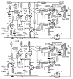
Distortion cancellation depends on each valve's individual distortion while the model shows an average for many valves. Same goes for hum cancellation with DHT. See DHT 100hz hum You have to select valves and over time the effect might be minimalised.I did some THD tuning on my breadboarded NFB SET (shown here Corona: An Ultra-Low Distortion A2 DHT SE Amp Prototype). There is quite a lot of distortion cancellation going on between stages and output transformer. THD and distortion profile can be "dialed-in" by adjusting the driver pentode's screen resistor (R18 in the schematic).
You are right that in triode one throws away the valve's strong point (output power) but there is another attraction in building a relatively simple 2x 5W amp (regarding psu and drive requirements) with just three bottles. No DHT hassle 🙂I'm quite convinced the best way to operate a tube is what it has been designed for. So, for E130L's it's a pentode PP amplifer, e.g. as Mona suggested many postings above.
I don't see any use in connecting a power pentode as a triode. With carefully implemented GNFB a pentode amplifier surely won't sound and behave worse than a triode one. Let alone it's better efficiency and higher output power capability. Maybe the main driver to do it anyway is just to be different?
Best regards!
Distortion cancellation depends on each valve's individual distortion while the model shows an average for many valves. Same goes for hum cancellation with DHT. See DHT 100hz hum You have to select valves and over time the effect might be minimalised.
The distortion cancellation will most probably change over time. However I can get similar results with many E130Ls having different characteristics.
How did you check the D%?🙂
Soundcard (MAudio Profire 610) with Pete Millett's soundcard interface. I made a bunch of measurements that are in the Corona-amp-thread. E.g. IMD Corona: An Ultra-Low Distortion A2 DHT SE Amp Prototype.
The results may be just luck but the design of the amp itself is the outcome of several iterations. I tried various schemes: SEP+GFB, Schade FB, triode, triode driver, pentode driver, mosfet-follower etc. The current version with pentode driver, mosfet follower and output triode was clearly the best combination of low distortion and low output impedance. One important factor is the Lundahl output transformer with quite high impedance (3k).
And even though the distortion cancellation may degrade over time I have no reason to believe that distortion would become ten-fold as predicted by the Spice models. Spice models are quite poor in predicting distortions in tube amps.
CAPS
Mona,
What 100uF caps did you use from O/P transformer primary to ground, also across the 1k2 resistor of 7N7?
Best Barry
Another one only tubes but with CCS 😀
The CCS screen resistor (82k) probably need adjusted to get the right current.
Mona
Mona,
What 100uF caps did you use from O/P transformer primary to ground, also across the 1k2 resistor of 7N7?
Best Barry
I am old and it's a long time I build something.Mona,
What 100uF caps did you use from O/P transformer primary to ground, also across the 1k2 resistor of 7N7?
In my good days one goes to local shop and buy what they hat in store.
Mona


Just plain elektrolytes. On 7N7 10 volts and on B+ 450V. It seems a negative supply is missing in the drawing. Something like 30V?
Yes it is definitely missing
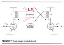
Dual Single Ended Amplifier Graeme Cohen Paper
This may be interesting to some.🙂
This may be interesting to some.🙂
Attachments

As painted pointed out the negative supply is missing, I'm assuming that the 330k resistors are connected to ground, should there be capacitors across the 7r5 cathode resistors?Looks like every one is fallen asleep here 😉 time to wake up 😛
Why not use some nice looking locktal tubes 😎
One side with, the other without, the decoupling C in the first stage to show the difference.
No delay on the high voltage needed, the auto bias turns on when the first 7N7 heats-up.
Mona
A bias voltage of just 600 mV would be too low even for a super high transconductance E130L. So, there's just the bias supply missing and no cathode capacitors necessary.
Best regards!
Best regards!
100 µF/350 Vdc would make a soup can as a film capacitor. Not too realistic at all.would they have been film or Elecrtrolytic?
Best regards!
You might check the power rating of crossover capacitors before applying them in a power supply where real currents govern. I once had a new Jupitor beewax capacitor explode below the advertised working voltage. Cured me for good 🙂
- Home
- Amplifiers
- Tubes / Valves
- E130L PP Power Amplifier