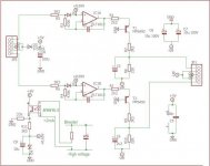
The negative voltage for the output tubes is supposed to come from the automatic bias circuit, see post #4 V4lve lover.Yes it is definitely missingOn 7N7 10 volts and on B+ 450V. It seems a negative supply is missing in the drawing. Something like 30V?
The reference to an optocoupler (left top amp schematic) is for the extension I made to the bias circuit for a delayed start.And the 7,5Ω cathode resistors are to get 80mA bias current.
Mona
Attachments
I havent figured out the bias completely yet, i have a large stock of 12VDC coil voltage reed relays, and currently im thinking of delaying the complete +5V to the bias servo, the reed relay will be switched by the same 555 per channel as the high voltage. I may also make a new revision of the plug-in boards to connect the supply voltage for the diode reference to the outside world.
Negative will be stabilised with a TL783/LM317HV with its positive output tied to ground, this is because i prefer this. I need to check with Barry wether there is enough AC on his transformers to lose a couple of volts over the TL783
I like your optocoupler mod, but i dont think it will work well enough, you may want to include a couple of zener diodes in series with the optocoupler LED to make sure there is a clean start-up signal.
No need to stabilise the negative supply, the circuit controls the bias voltage to get the right tube current independent of the negatieve voltage as long as there is enough.Negative will be stabilised with a TL783/LM317HV with its positive output tied to ground, this is because i prefer this. I need to check with Barry wether there is enough AC on his transformers to lose a couple of volts over the TL783.
The start-up may well be slow, gives only a also slow raise of the bias current.I like your optocoupler mod, but i dont think it will work well enough, you may want to include a couple of zener diodes in series with the optocoupler LED to make sure there is a clean start-up signal.
Mona
PP E130L
I have built/breadboarded a version of your design but with CCS from O/P of
6N6P's Anodes, the problem I have is that there is 75v coming from one CCS & 95V coming off the other (6n6p's that I have are pretty well matched & individual CCS's are set at 20mA for testing) , I am thinking that this because 1M resistor linking the two grids, could this be the case here? Apart from this problem everything else functions as it should.
regards
Barry
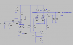
I don't have E130L tube model, but I used quite similar Svetlana's EL509 model to build a simulation of the full amplifier.
This is what I got:
I have built/breadboarded a version of your design but with CCS from O/P of
6N6P's Anodes, the problem I have is that there is 75v coming from one CCS & 95V coming off the other (6n6p's that I have are pretty well matched & individual CCS's are set at 20mA for testing) , I am thinking that this because 1M resistor linking the two grids, could this be the case here? Apart from this problem everything else functions as it should.
regards
Barry
With that much current (10mA) the grid voltage is very low (less than 1V).The grid current starts, giving a voltage drop over the 1M resistor.That makes the grid more negative and the anode more positive.
Mona
Mona
I dropped current from 20mA to 10mA, there is still a difference of 15volts between triodes, should I reduce resistance? E130L's grids set at -27.6v
Why so much current, 3...4mA is enough.I dropped current from 20mA to 10mA, there is still a difference of 15volts between triodes, should I reduce resistance? E130L's grids set at -27.6v
You need an output swing of +27V and -27V with that output bias.
At the lowest point (-27V) that anode voltage must be reached with -Vg not closer to zero then 1V to avoid grid current.And even then there will allways be a difference, normal for such a phase inverter.
Mona
OK, I'll try it at lower current, it was just that I had read that the 6N6 can sound a little lifeless running at low current. Was this the reason that you had 2 different plate resistor values?
If you read the discusion , without current source in the common cathodes the plate resistors must be different for equal output voltage swing .
For a differential amplifier the ccs in the tail is the most important , then it will be balanced automatically ... you did it in a odd way 😀
For a differential amplifier the ccs in the tail is the most important , then it will be balanced automatically ... you did it in a odd way 😀

I am using individual ccs om anodes of 6n6p not a single one on the tail, this strategy was recommended by Ale Moglia, so anode resistors are not used, I might well put one in 5.6k one in on one side to achieve similar voltage also, I can't get current as low as 3-4mA, 5mA was the lowest here might need to change lower fets for something else (J310)With that much current (10mA) the grid voltage is very low (less than 1V).The grid current starts, giving a voltage drop over the 1M resistor.That makes the grid more negative and the anode more positive.
Mona
So what you are saying is to put the plate (27k & 33K)resistors in & just use a single CCS in the tail & not the way I've done it how about leaving it the way it is & put about 6k of resistance on one plate? Would that not achieve the same goal?If you read the discusion , without current source in the common cathodes the plate resistors must be different for equal output voltage swing .
For a differential amplifier the ccs in the tail is the most important , then it will be balanced automatically ... you did it in a odd way 😀
I started this thread asking for some ideas, it might be a good idea if painted read what I wrote, the clue is BREADBOARD!
Can be usefull to drive output tubes but not for a phase splitterI am using individual ccs om anodes of 6n6p not a single one on the tail, this strategy was recommended by Ale Moglia, so anode resistors are not used
A resistor in series with a CCS only steals voltage from the CCS, anode voltage doesn't change.I might well put one in 5.6k one in on one side to achieve similar voltage
With a jfet there is a max current, not a minimum unless there is not enough voltage for the CCS.also, I can't get current as low as 3-4mA, 5mA was the lowest here might need to change lower fets for something else (J310)
Mona
Would you remove CCS here & put one on the tail to drivr both triodes?Can be usefull to drive output tubes but not for a phase splitterA resistor in series with a CCS only steals voltage from the CCS, anode voltage doesn't change.With a jfet there is a max current, not a minimum unless there is not enough voltage for the CCS.
Mona
Painted has an excellent idea for you 😛I started this thread asking for some ideas, it might be a good idea if painted read what I wrote, the clue is BREADBOARD!
Attachments
- Home
- Amplifiers
- Tubes / Valves
- E130L PP Power Amplifier