Painted has an excellent idea for you 😛
If you actually read that book Morgan Jones suggests doing it the way I have, as does Ale Moglia
Attachments
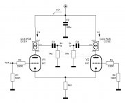
As said by Depanatoru in #169, a CCS in the LTP tail is much more reasonable than two as plate loads.
I don't know which edition of Morgan Jones' book you've got, but I think I've found what you mean in the 3rd one. And he did a really big mistake there: He provided a tail CCS as well as two plate load CCS's for a two triode LTP. This arrangement won't work at all, as the cathode CCS fights against the two plate CCS's, with the poor triode pair in between that apparently doesn't know what to do.
About ten years ago I cheerfully copied his schematics, using a 6N23-EV double triode, etched a PCB - and was wondering why it didn't work at all. Thinking thoroughly about it lend me to the above mentioned solution.
Btw, this isn't the only error I've found in that book 🙄.
Best regards!

A circuit like that only function with also a CCS at the cathodes.
Here the current in Rk1 is the sum of CCS1 and CCS2. So the current doesn't change and so the cathode voltage will stay at a fixed level.
Like that there is no change from the left tube passed to the right one and no output on O-, only on O+.
Mona
Here the current in Rk1 is the sum of CCS1 and CCS2. So the current doesn't change and so the cathode voltage will stay at a fixed level.
Like that there is no change from the left tube passed to the right one and no output on O-, only on O+.
Mona
Etiquette!
Here's a book for You!Painted has an excellent idea for you 😛
If you actually read that book Morgan Jones suggests doing it the way I have, as does Ale Moglia
Attachments

In addition, I'd regard it as simply impossible to adjust the cathode CCS current precisely to the sum of both plate CCS currents - and keep it stable at all conditions, especially with temperature changes.
Best regards!
Best regards!
As said by Depanatoru in #169, a CCS in the LTP tail is much more reasonable than two as plate loads.
I don't know which edition of Morgan Jones' book you've got, but I think I've found what you mean in the 3rd one. And he did a really big mistake there: He provided a tail CCS as well as two plate load CCS's for a two triode LTP. This arrangement won't work at all, as the cathode CCS fights against the two plate CCS's, with the poor triode pair in between that apparently doesn't know what to do.
About ten years ago I cheerfully copied his schematics, using a 6N23-EV double triode, etched a PCB - and was wondering why it didn't work at all. Thinking thoroughly about it lend me to the above mentioned solution.
Btw, this isn't the only error I've found in that book 🙄.
Best regards!
Yes You are correct,I have the third edition.
I will now remove one CCS & put just one on the tail, thankyou to all the the
constructive People out there, I am "not", as you've already guessed & never professed as much an expert!
When experts don't get it right, us mere mortals are lead up a blind alley with an empty wallet
From other recommendations I've seen, I think this is the definitive tome ...
Radio Designers Handbook V4
Radio Designers Handbook V4
In addition, I'd regard it as simply impossible to adjust the cathode CCS current precisely to the sum of both plate CCS currents - and keep it stable at all conditions, especially with temperature changes.
Best regards!
That is fundamental mistake , he mistook current mirror loads from many transistor diferential amplifiers for 2 current sources 😀
The circuit must work well if you do it in the right way . The gain should be signicant higher
Last edited:
Yeah, for higher gain pentodes or cascodes might be preferable. If there's also demand for even higher output levels, bootstrapping the plate resistors is an option.
Best regards!
Best regards!
As said by Depanatoru in #169, a CCS in the LTP tail is much more reasonable than two as plate loads.
I don't know which edition of Morgan Jones' book you've got, but I think I've found what you mean in the 3rd one. And he did a really big mistake there: He provided a tail CCS as well as two plate load CCS's for a two triode LTP. This arrangement won't work at all, as the cathode CCS fights against the two plate CCS's, with the poor triode pair in between that apparently doesn't know what to do.
About ten years ago I cheerfully copied his schematics, using a 6N23-EV double triode, etched a PCB - and was wondering why it didn't work at all. Thinking thoroughly about it lend me to the above mentioned solution.
Btw, this isn't the only error I've found in that book 🙄.
Best regards!
In the 4th edition he explains the same circuit but the smoking gun is hidden in the text.
The impedance of the tail ccs vs the load ccss have to differ so they don't fight each other.
For example you go with a cascoded ccs for the tail and a single element ccs for the loads. Even a triode is ok, like in a differential SRPP with a cascoded ccs tail.
I made such a thing all with ecc88 tubes and the result is great as long as the srpp tubes are extremely well matched.
I have 400 ecc88 at hand and a uTracer so it was easy for me.
I don't think it will be stable in a long run tho... tubes age.
Best regards,
Silviu
Active loads are a kind of weak current sources , but different that's why are not named current sources . Much weaker than the ones from the book ... not 1 transistor vs 2 cascoded transistors . And for a differential amplifier must be mirror active loads , not independent . If one goes up the other goes down by the same amount of current . Only in this wat are not "fighting" with the true current source from tail .
Last edited:
In Post 181 don't the following grid resisters R3 & R4 defeat the purpose of a CCS in the plates anyway.🙂
I've decided to run with drawing & run without CCS for now, still got a big difference in voltage of each triode. I do have another problem that needs addressing in as much my B+ at idle is 403V, this is because the Transformers I have are too high on voltage, needs to be regulated down 100V. I don't think it will work too well with resistor droppers because of variable current draw. I have regulated G2 with VR Tubes & CCS which is working, I have grid bias controlled from separate 60V supply set at 27.6V, I ordered Trannies as that was what I was told I needed, but hey ho that my fault.
He provided a tail CCS as well as two plate load CCS's for a two triode LTP.
Btw, this isn't the only error I've found in that book 🙄.
same here, not a book I would recommend, to many flaws, and tail and plate CCS without at least some resistance in parallel is so gross an error I wonder what he was thinking
That's a medium power tetrode, not very usefull here.
The schematic I posted with 7N7 will accept the 6N6P too without changes.
Mona
Ok Mona,
I have everything up to screen of E130L working good, all voltages are good, have 144V fixed on G2, B+ is a little on the high side, but I can't get power tubes to conduct properly, I can only get about half a milliamp across 1 ohm cathode resistor on each tube, grid bias was initially set at -27.6V its adjustable between -23 & -41V, this can also be measured on pin1 of E130L. I have 6 tubes, they are all the same, 4 are new.
regards
Barry
The pentode curves for g2 = 150V show that -20V on g1 gives very little current. At -23V probably still cutoff.
In post #4 g1= -17 was stated.
In post #4 g1= -17 was stated.
- Home
- Amplifiers
- Tubes / Valves
- E130L PP Power Amplifier